Locomotive Engineer Darrin Crone provides us with an insight into recent weeks’ work on restoring the great locomotive.
Week commencing 30 December
The dragbox reaming continued this week. This has turned in to a time-consuming job as there are a number to do and they are deep holes. I must thank the patience of those taking their turn with this job. On Thursday I examined the results so far and I think the end is in sight.
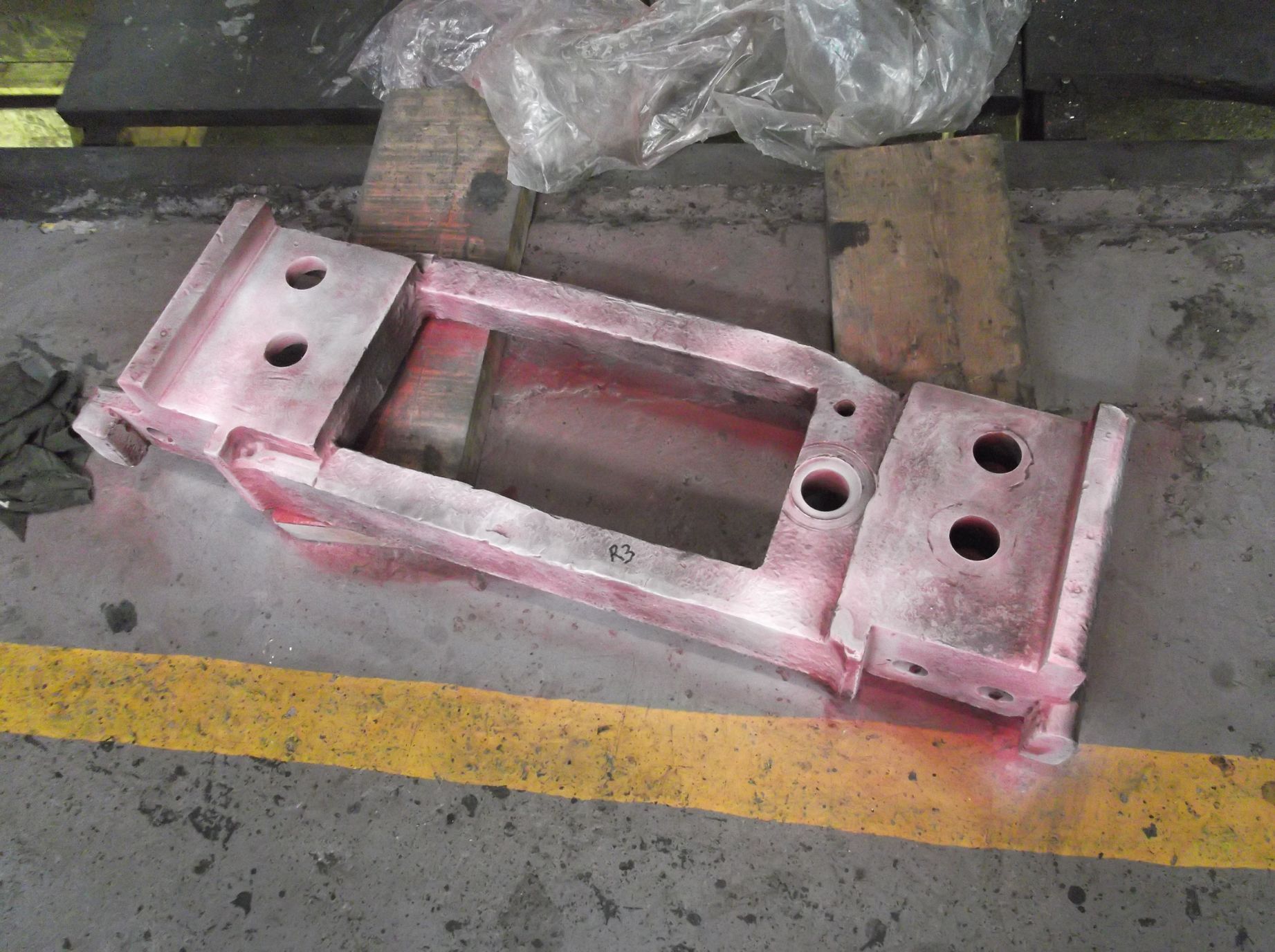
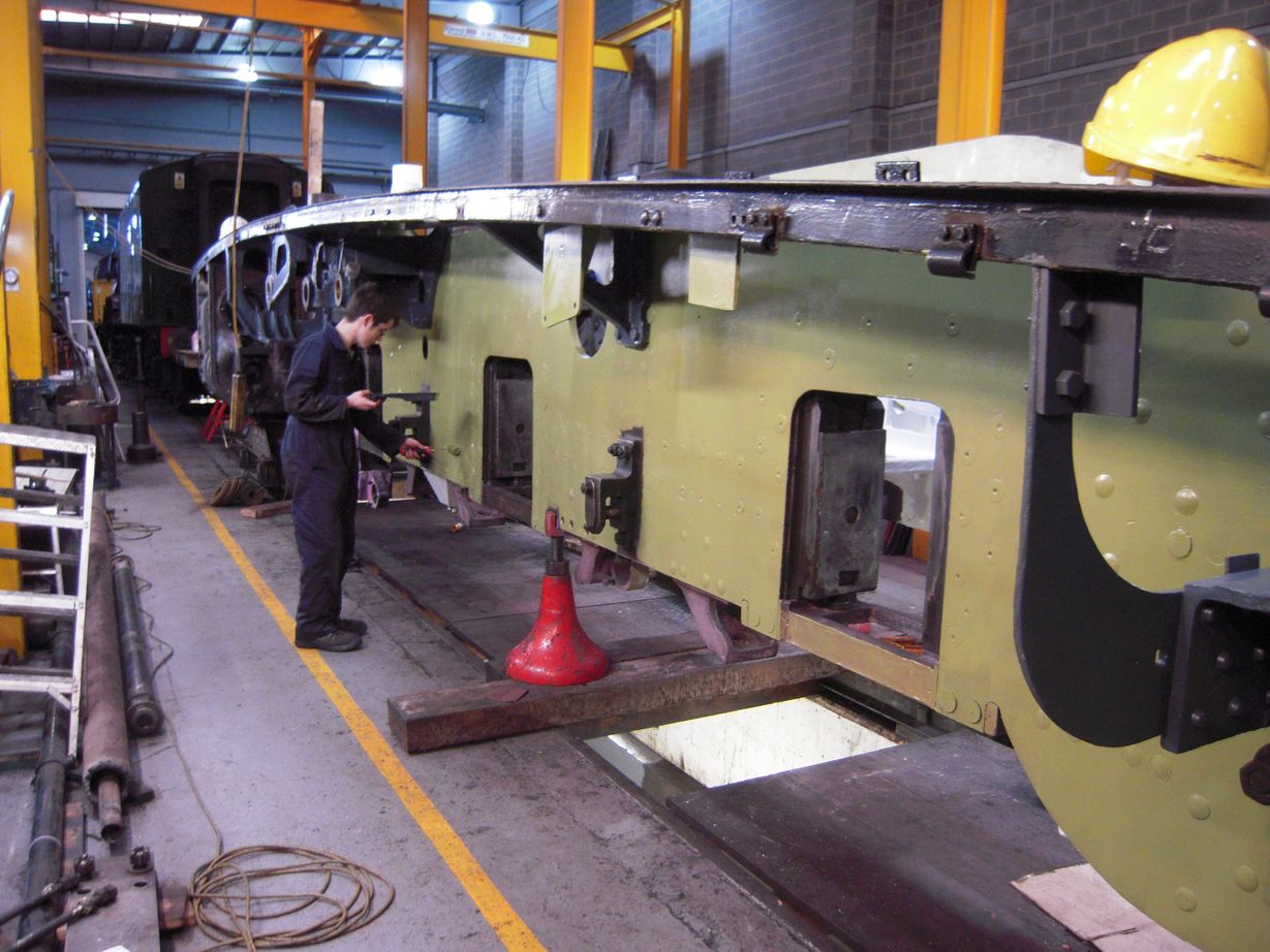
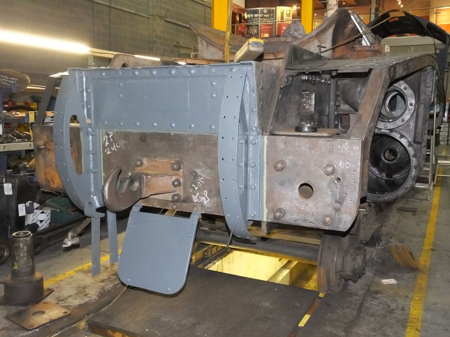
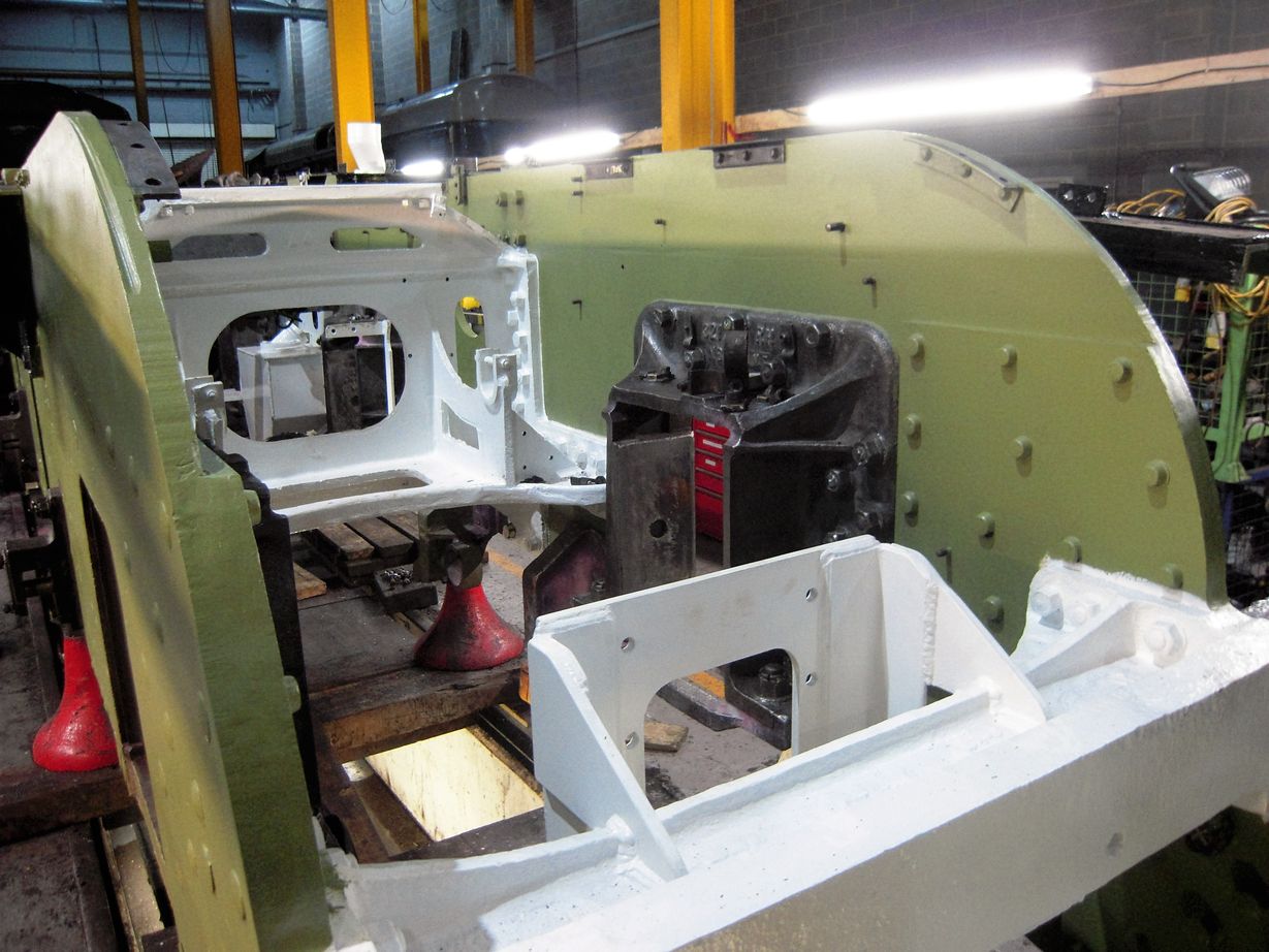
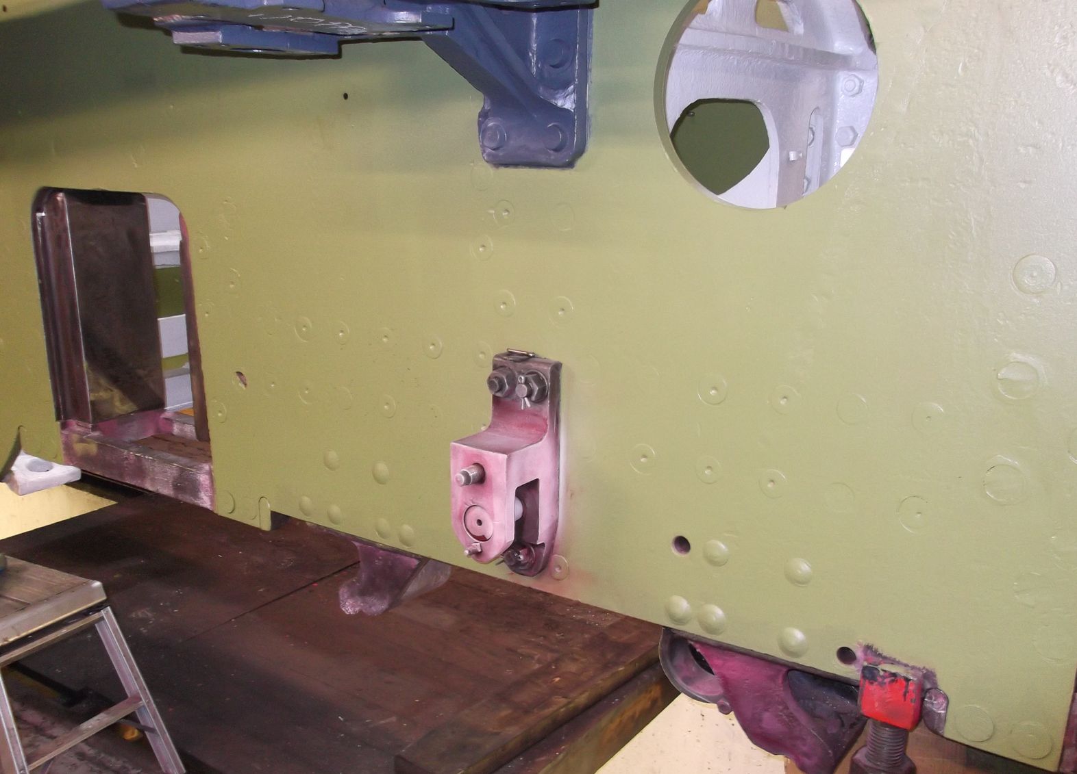
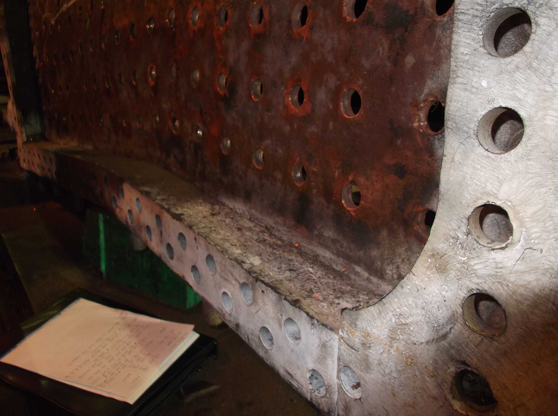
Painting continued this week with primer now being put onto the forward sections of the inner and outer Cartazzi frames. Elsewhere, the Painting Team have applied further coats to the large “+”-shaped stretcher and continued on the footplating, which has also seen the attention of the welder. As previously reported, the footplating has cracked in service and is being welded up. The right-hand side is now complete and some prep work has been done to the left side.
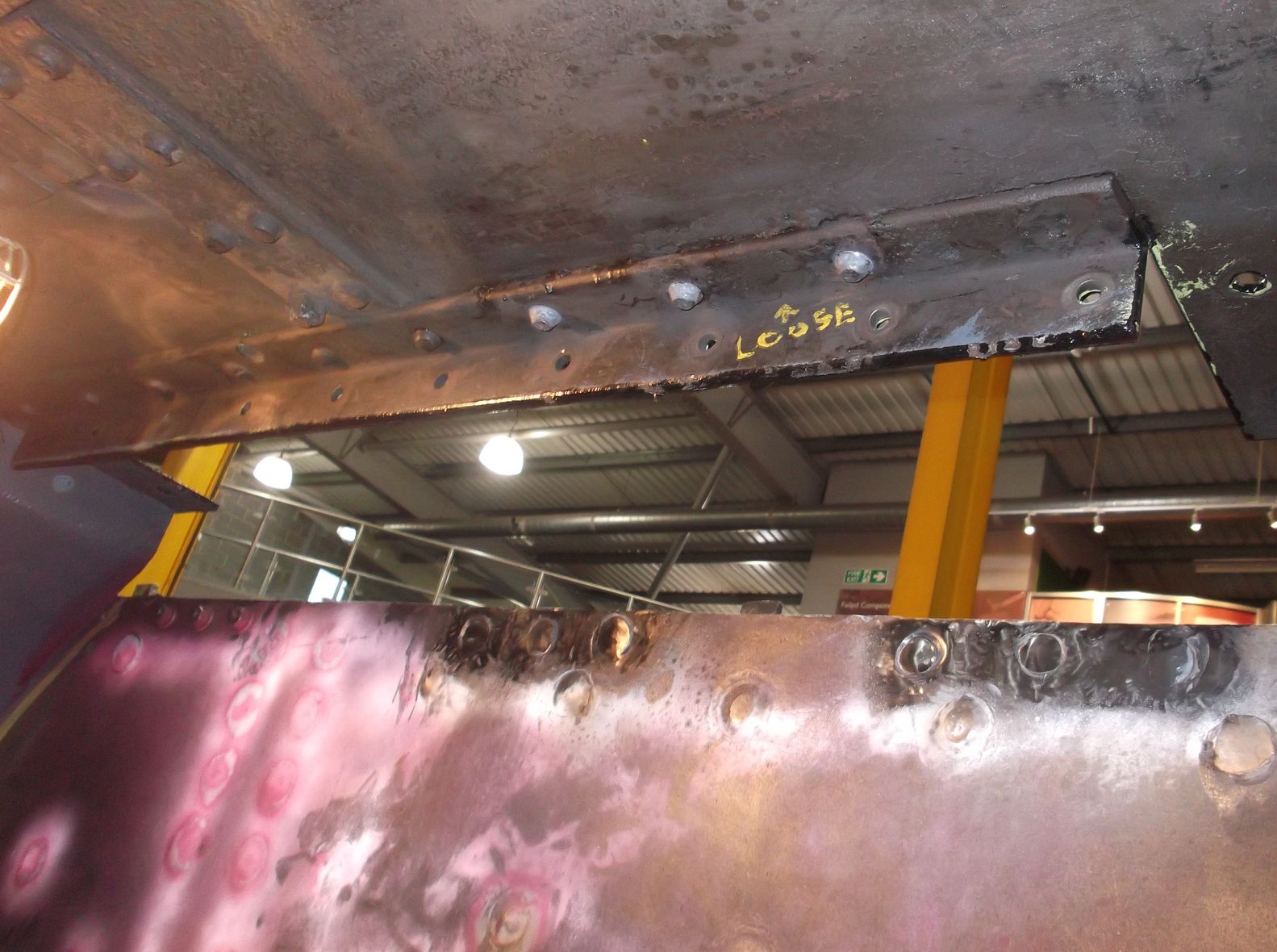
The footplating has also seen the replacement of the loose rivets around the brackets where the splashers are secured. The loose rivets were identified during the frame survey and were then removed. On Friday the Riveting Team replaced the rivets on the long angles that fasten the outside of the leading splashers to the footplating. The frame/splasher brackets were also re-riveted, where we could access them. There are a number that are inaccessible with the setup we have, but we have a plan.
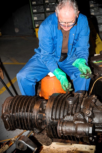
The valve liners were removed before Christmas and the steam chests now need cleaning out and preparing so that we can take measurements in preparation for ordering the replacements. The right-hand steam chest has now been cleaned out. Later in the week cleaning of the air pump continued – this is one of the most difficult items to get clean due to its complicated shape.
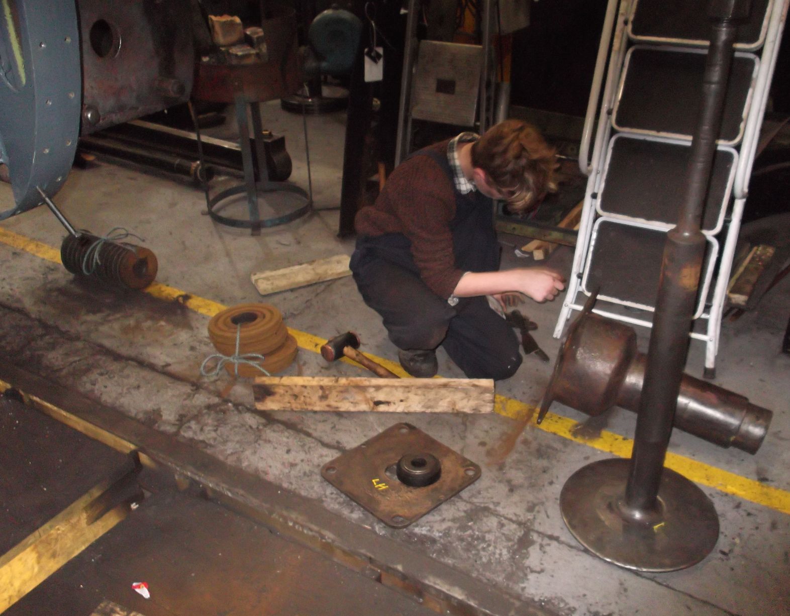
The Engineering Team are now removing the hornstays to assess their fit and to examine them for damage and cracks. The trailing set were removed and after cleaning were “di-penned”. After detailed examination they were declared free from defects. They were then refitted. Their fit is good so they should not require any work, though it has been decided to fit new securing bolts at this overhaul.
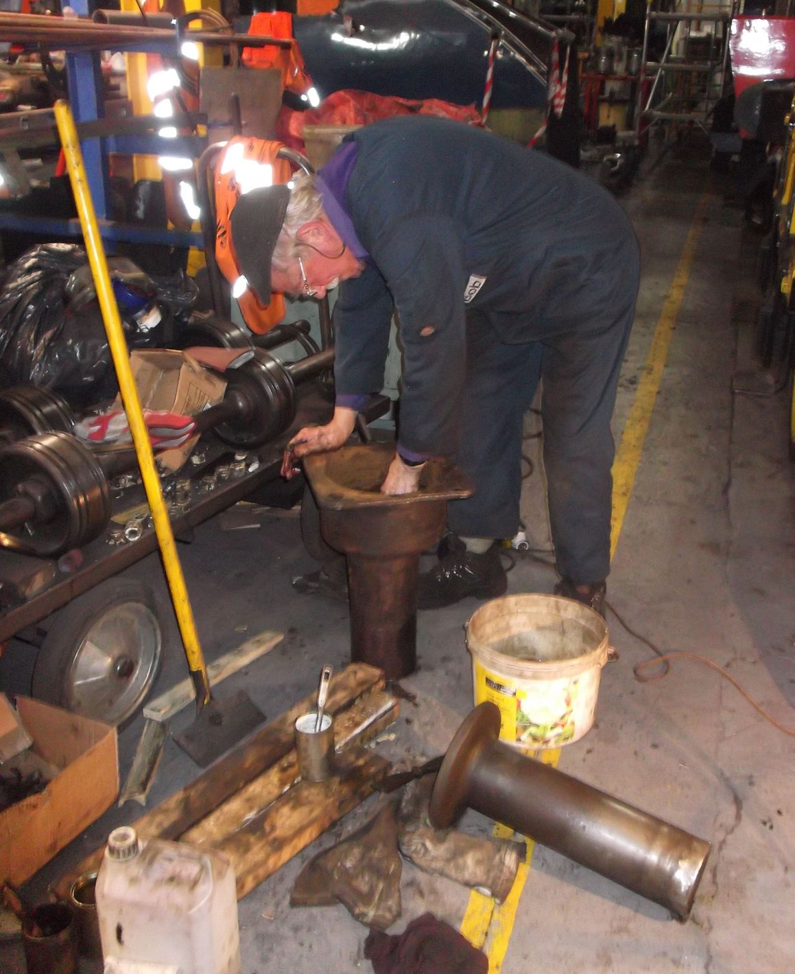
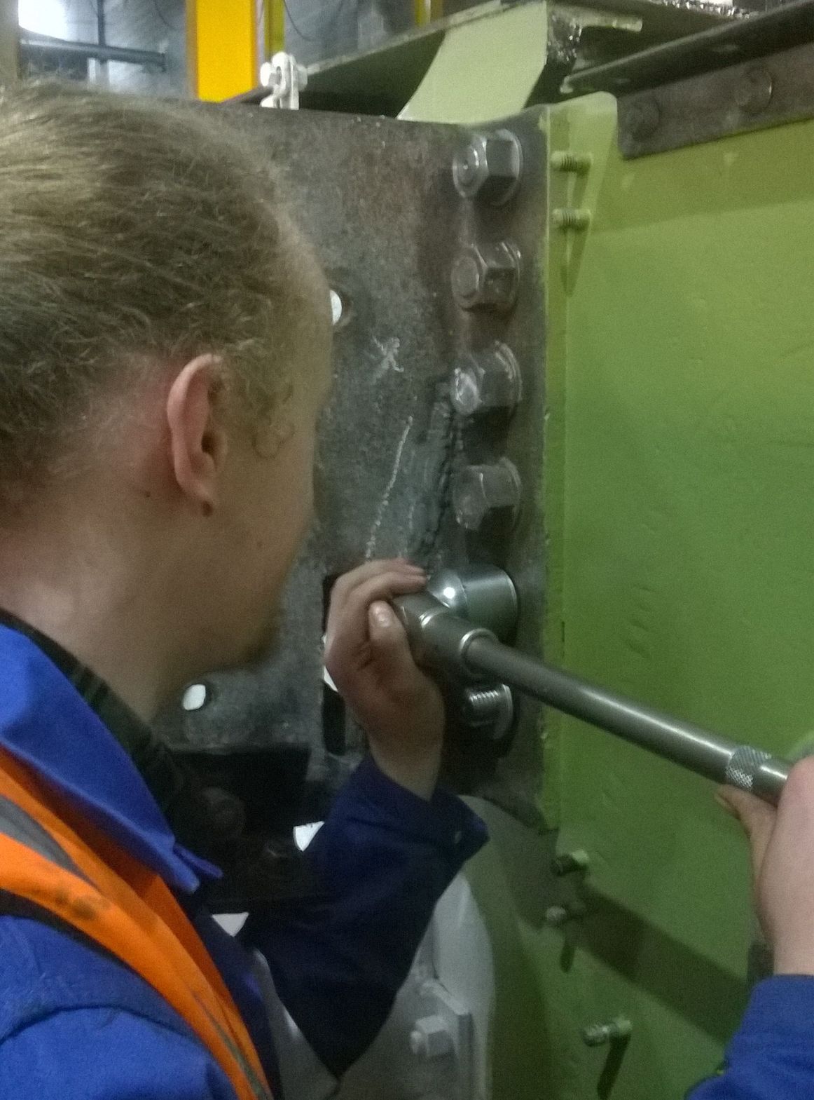
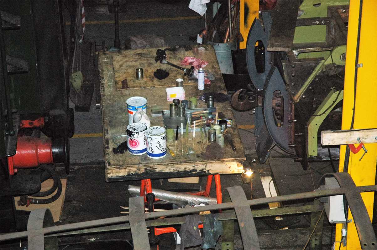
On Saturday we had a productive “007 Gang” (Junior Volunteers) working day. Both buffers were removed and dismantled. A start was made on cleaning the components and the buffer housings on the loco.

Week commencing 6 January
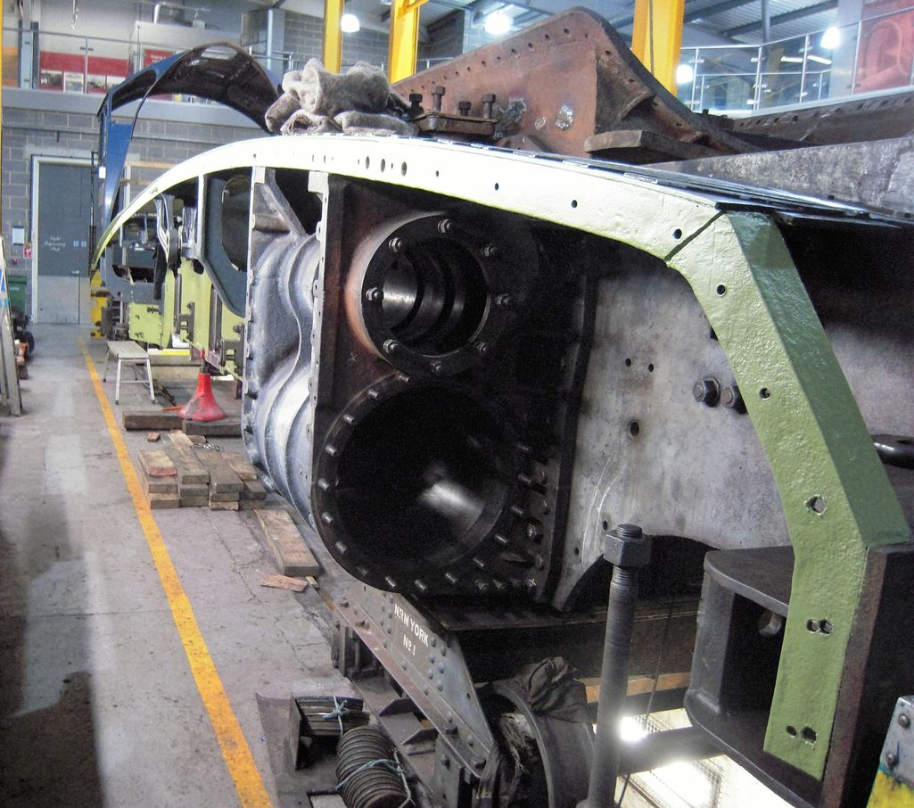
Battle recommenced on the removal of the middle cylinder cover studs. Though slow, we are making progress with this and by the end of the week there will be just one full stud left – however there are a small number that have broken and will require drilling out. Of course, the broken ones are also the least accessible. The Engineering Team are now working on the design of a jig to ensure accurate drilling of the broken studs, as we cannot risk any damage to the cylinder casting by wayward drilling.
We haven’t worked on the bogie for some time as the Engineering Team have been fully occupied on the the loco frames. In the meantime, the bogie had been moved to allow Rocket’s boiler to be placed where it could be dismantled for overhaul. Where the bogie was moved to was unsuitable for further work. However, with the removal of some of the racking from the workshop we identified an area where we could put the bogie and work on it. With the agreement of the National Railway Museum’s Workshop Manager, a trio of Engineering Team Leaders skilfully moved the bogie frames to an area with plenty of room to recommence work.
Painting has continued this week with primer being applied to the main frame plates for the first time in this overhaul. Ahead of the painters, other team members have been attending to any prep work prior to painting. With the removal of the buffers this has required descaling and cleaning around the buffer housings and the bufferbeam itself.
The front buffers carry some damage from a historical heavy shunt. They are fully serviceable but can’t be fully dismantled for cleaning and inspection. So this week the repair of the buffers and careful dismantling began. Whilst at the bufferbeam the removal of the left-hand buffer has allowed the replacement of a loose rivet identified during the frame survey. This was replaced by the Riveting Team on Friday. At the same time a rivet was replaced on the bufferbeam to mainframe bracket behind the same buffer.
At the dragbox, reaming was completed this week. Well done to everybody who has taken a turn on this job. A magnificent result has been obtained all by hand in an inaccessible location. We also used the magnetic clamp drill for reaming this week to clean up some holes that were very close to available machine reamers that the National Railway Museum loaned us. The fitted bolts for the reversing shaft vacuum clutch were roughed out on Saturday but require final machining and fitting.

Next to the frames, cleaning of the air pump and preparing it for overhaul continued with the strainers and cladding being removed and cleaned.
The inspection and assessment of the hornstays continued this week with the centre/driving hornstays. Both were dye-penetrant inspected and were found to be flaw-free and were then refitted to the engine. Further inspection work this week was carried out in the steam chests where the valve liners have been removed. This critical area requires careful assessment as the new liners have to be a good fit. After assessment it will be decided if any reconditioning of the casting is required.
Week commencing 13 January
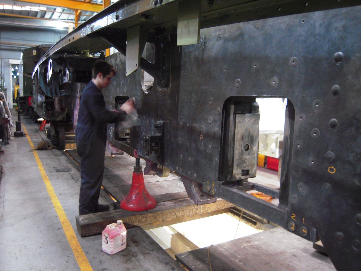
The main activity of the week is the continued painting of the frames with the inside of the frame plates receiving their first coats of primer. Paint is also now being applied to the underneath of the footplating and angles. In front of the painters there has been plenty of needle-gunning and cleaning to be done. The last couple of footplating fractures were welded up this week. To the side of the frames the air pump is being cleaned inside and out.
The buffers were taken apart this week by carefully removing material from the inner buffer to allow its removal from the outer housing. With these parts separated they were then cleaned out of the thick accumulations of grime that had collected and they will now be reconditioned before reassembly. The buffers have backplates that fasten to the back of the buffer housings. The fixing holes were cleaned out and re-tapped. Broken studs in the buffer housings will require removal to allow the backplates to be refitted.
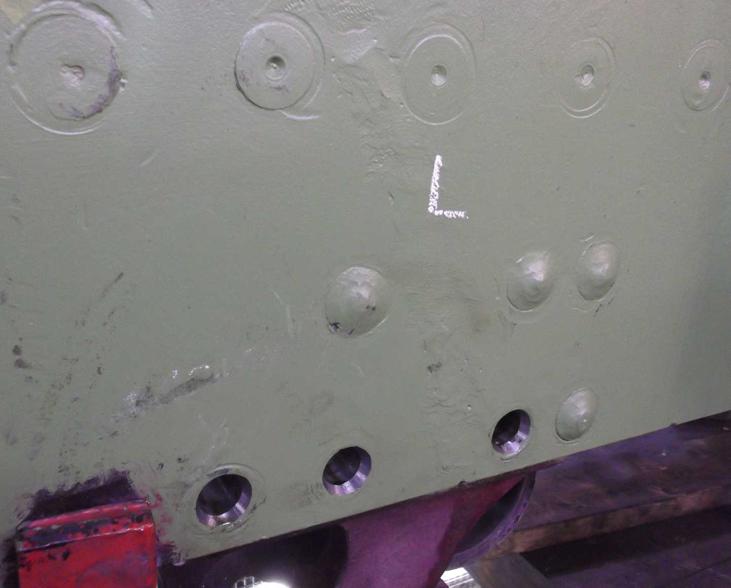
The frame plate to the rear of the left-hand cylinder casting, which was hidden behind the left-hand leading sandbox, was “di-penned” this week. After detailed inspection is was declared defect-free and was then primed. The outside of the mainframes up to the cylinder castings has now been primed. Further areas subject to flaw detection this week included the brake hanger brackets. These were given a final clean and the test fluids applied. No faults were found.
Reaming of the spring bracket holes – where loose rivets were removed from the frames – has been carried out intermittently over the last few weeks. It has been difficult to obtain an acceptable finish to these holes as they have been welded up in the past and no matter how hard we try, the adjustable reamers leave “chatter” marks due to the uneven hardness in the holes.

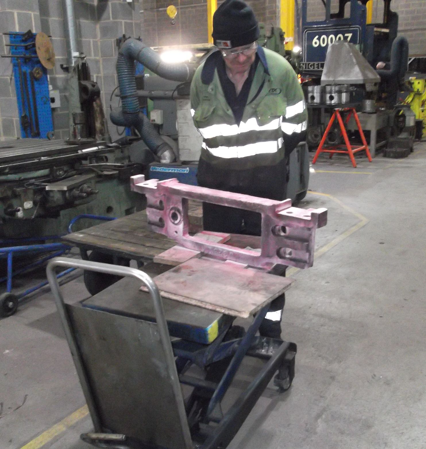
This week Malcolm Bateman used the mag-drill with machine reamers and a number of holes were finished ready for new rivets. We prefer to use an adjustable reamer as it removes less material than having to increase a hole size up to a fixed size reamer. The worn fitted bolts that secured the frame stretcher that holds the vacuum lock were replaced this week. New bolts were finish-machined and have now been fitted.
The horn cutout of the trailing right-hand at one of the top corners was found to be quite roughly cut. This is historical, however this is also a highly stressed area on the frames so to remove any potential crack initiators the area was carefully smoothed.
The steam chests – where the valve liners were removed – have been cleaned of carbon deposits. These areas were previously made inaccessible by the liners. Careful cleaning is required to ensure a good fit from the new liners and this work will continue. Measurements have been taken and it appears these confirm no change from last time the liners were replaced. Quotations are now being sought for the supply and fitting of new liners.
The removal of the middle cylinder cover studs continued this week. A drilling jig has been constructed to accurately drill out the remaining studs. The jig worked exactly as planned and we were able to drill out a stud to tapping size and to remove the remnants with the point of a scriber.

The hornstay removal and inspection was continued this week with the leading right-hand. This hornstay seems to have received quite a battering over the years so a considerable amount of time had to be spent in cleaning up the burrs from its bottom outside edge. The burrs were ground off then the grinding marks were removed to give a smooth finish. It was then visually inspected and decided that it would require further work, however so as not to leave the frames unsupported the hornstay was refitted and it will be revisited next week.
Week commencing 20 January
The boiler was visited this week at Llangollen by our Chief Mechanical Engineer Richard Swales and myself. At Llangollen we met with our Engineering Team volunteer Paul Aston, who is doing a great job of interfacing with the Llangollen Engineering Team and provides weekly reports and photographs so we are very well informed of progress. During our visit we also met with our boiler insurance surveyor, Llangollen Railways’ head of engineering and their boilersmith.
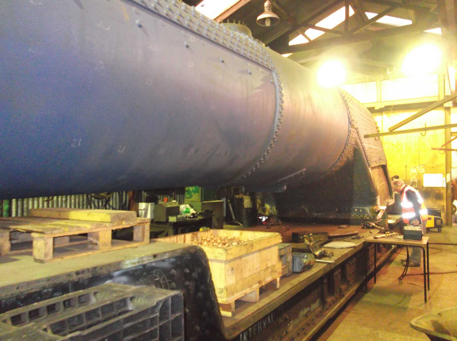
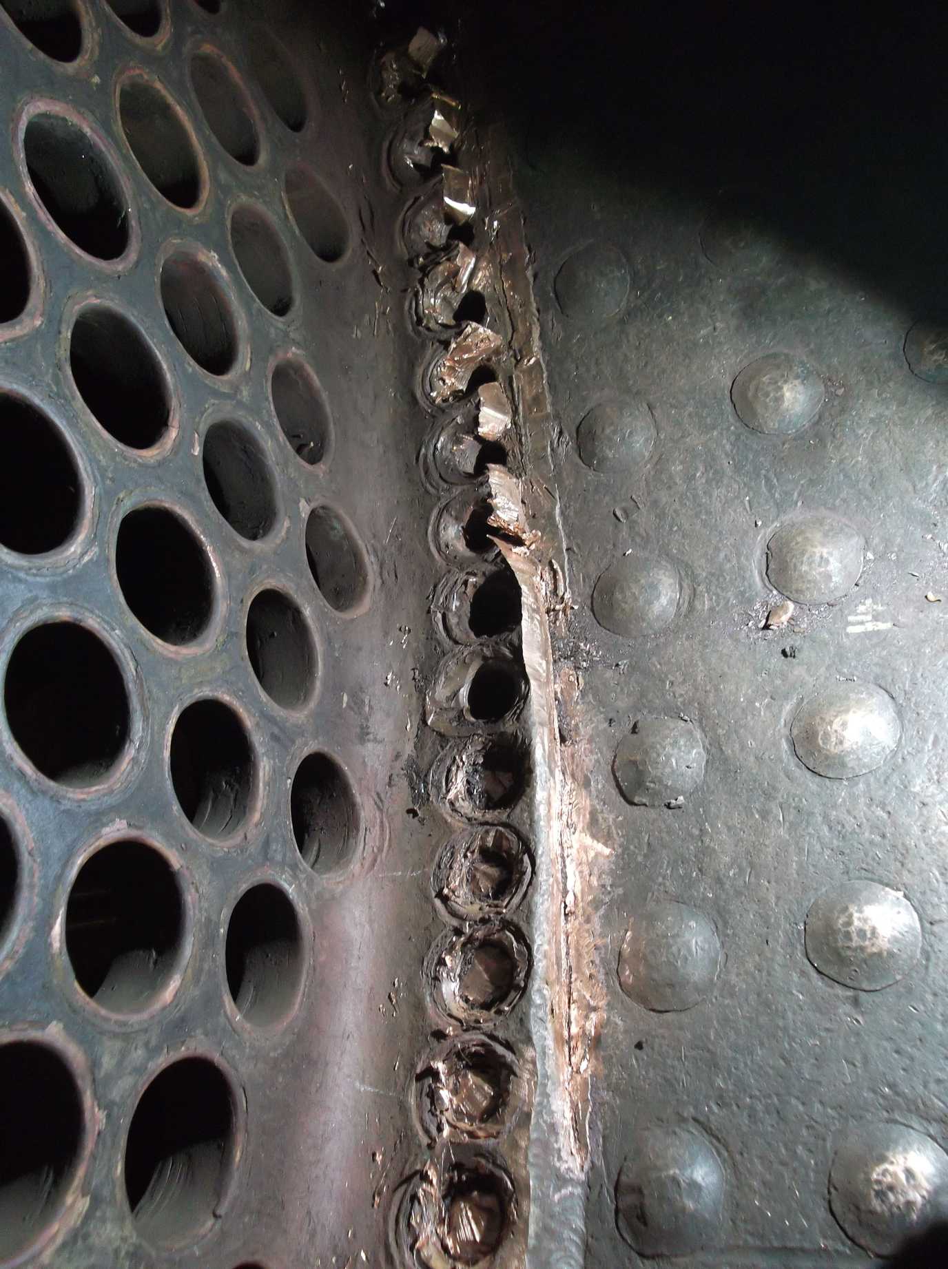
Work on the boiler is now well underway and it has been moved into the boiler shop from the main workshop area, where work was initially being carried out. Sections of the outer wrapper and outer doorplate have been removed with their stays drilled out. Some of the stays are at maximum size now so the holes will require welding up. As you may know, each time a stay is replaced it is normal practice to increase the size of the hole as the threads need to be cleaned up to ensure a good fit between plate and stay. So, as a boiler is re-stayed during its life, the stay threads get bigger. This is permissible up to a certain maximum size at which the holes need to be closed up – normally welded – and remade.
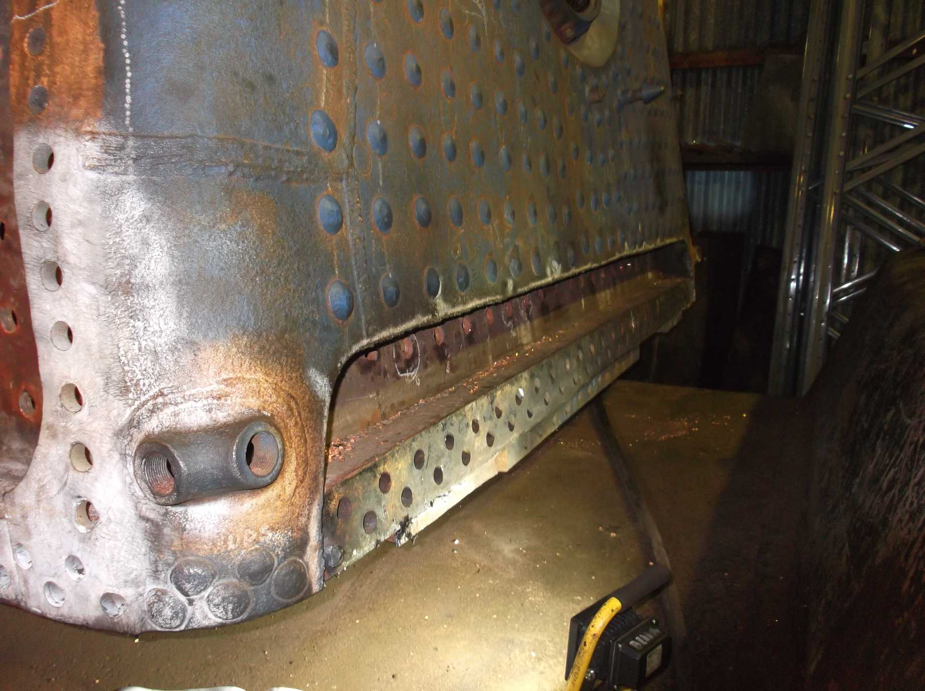
Work on the boiler has also included progress with the removal of the firebox tubeplate. The tubeplate is secured with patch screws and has been seal-welded in. The weld and patch screws are in the process of being removed.
After visiting Llangollen, Richard Swales and I went to LNWR at Crewe to see work on our new copper tubeplate. The tubeplate has been cut out from plate and has been machined to reduce the thickness of the flange, as specified by the manufacturing drawing. It is now ready for forming. On our visit it was on the former ready to be shaped.

While considering progress away from York, we have been in contact with our wheel repairers at Buckfastleigh. Work progresses on the wheelsets with the bogie wheels being on the lathe with further machining to remove the lining plates while the coupled wheels are receiving some repair work.
At York, work continued with the removal of the middle cylinder studs. There are only two studs remaining that will require cutting off before they can be drilled out. A guard has been made to go round the studs to make sure the face of the cylinder casting is protected when the studs are cut. Also competing for space near the middle cylinder, work continues on preparing the steam chests for final inspection and the fitting of new valve liners.

Reaming and countersinking some of the spring bracket rivet holes was completed this week, now that the reamer we needed had been sourced. All the spring bracket holes are now ready for riveting.
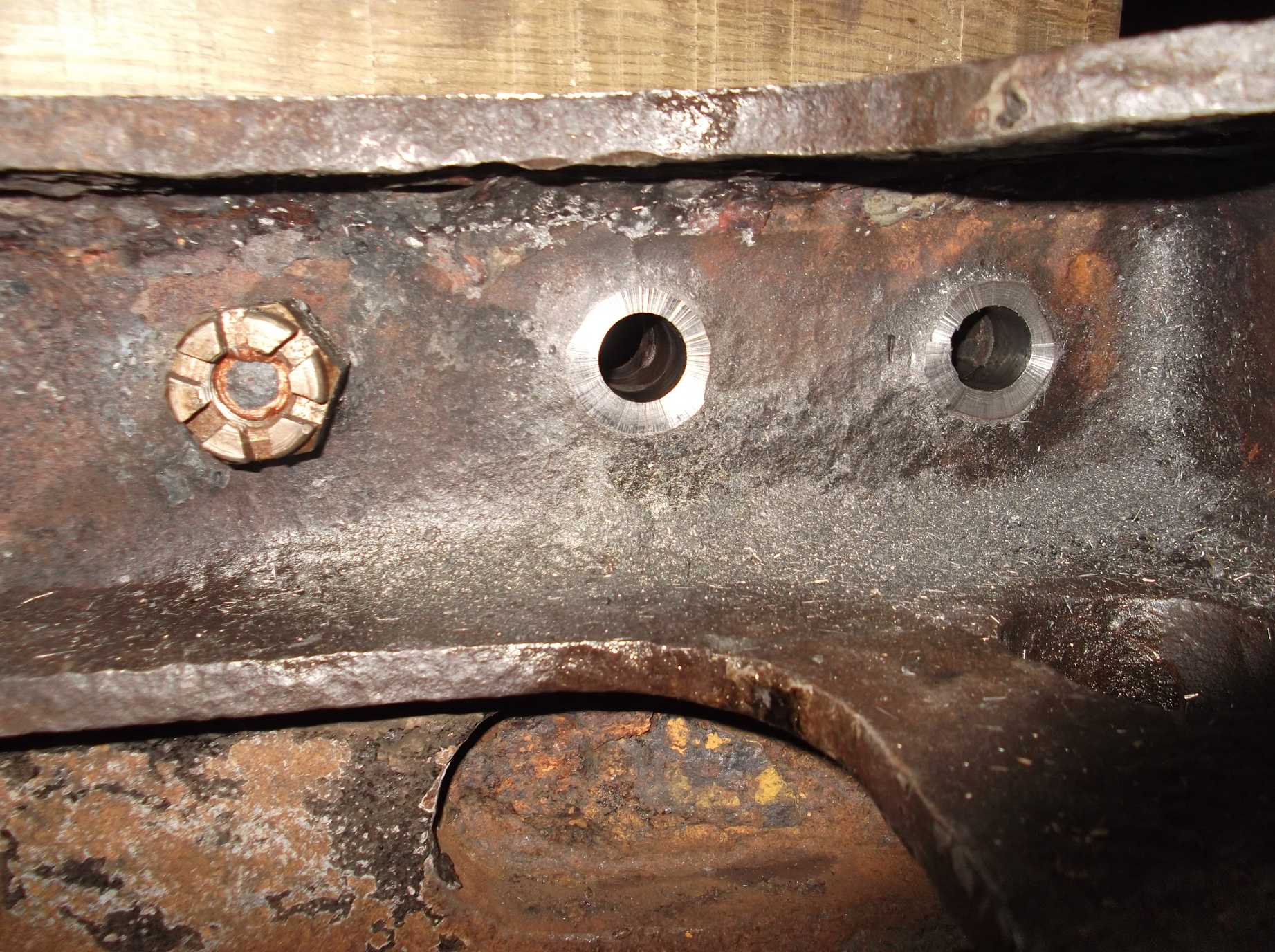
Work resumed at the dragbox this week. It took weeks of effort to manually ream out the dragbox holes but the uneven surface around the holes is unsuitable for tightening a nut onto when we fit new bolts. It was decided that the holes needed spotfacing. This involves cutting a flat surface around the bolt holes with a special cutter.
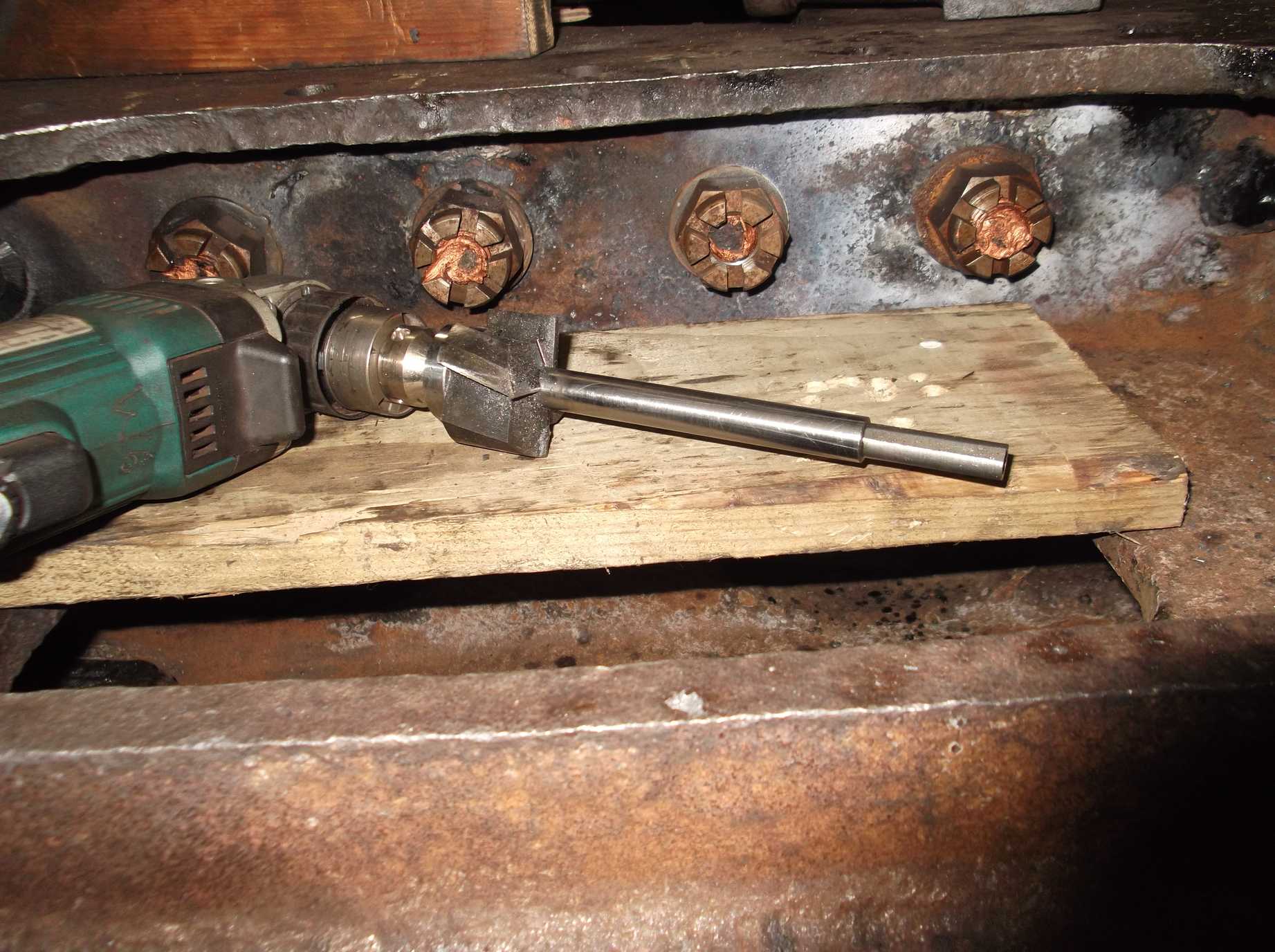
After discussing this with one of the volunteer Engineering Team members last week, he brought in a spotface cutter mounted on a spindle that he had made in his home workshop. A close fitting bush is fitted in the hole and the spindle runs in it, keeping the cutter square to the hole. It was used this week and three spotfaces were cut. It’s another slow process due to the space only allowing a small electric drill to be used.
Painting this week continued on the frames and black gloss has been put on the mechanical lubricator bracket ready for the lubricators to be refitted. Further prep work for painting around the front-right footplating managed to loosen a few more footplate rivets. The burning gear was out this week and a few more loose fasteners were removed that were identified for replacement. The holes are now being prepped for new rivets.
The front buffer housings have been cleaned out and given an anti-corrosive coating inside by Malcolm Bateman. The buffer housings had also worn to a sharp edge at the front so this was dressed to a less aggressive radii. Malcolm also retrieved our gauge frame components from store as we are now beginning a programme of boiler fitting overhaul so that everything is ready for the boiler when Llangollen require them.

The air pump cleaning was completed this week. We will now begin to dismantle the pump and begin its repair.
The last of the hornstays was removed for inspection this week. The leading right was removed last week but needed more work so was removed again this week. When the leading left was removed that also needed a considerable amount of tidying up. Both the leading hornstays seem to have had a very hard life so it has been decided that both should be removed and will receive further repairs.
Week commencing 27 January
The remaining two middle cylinder cover studs were removed this week using the drilling jig, which has proved to be very effective in directing the drill down the centre of the stud accurately. One of the final two stud threads was actually removed intact – the stud holes now need cleaning out and new studs can be fitted.
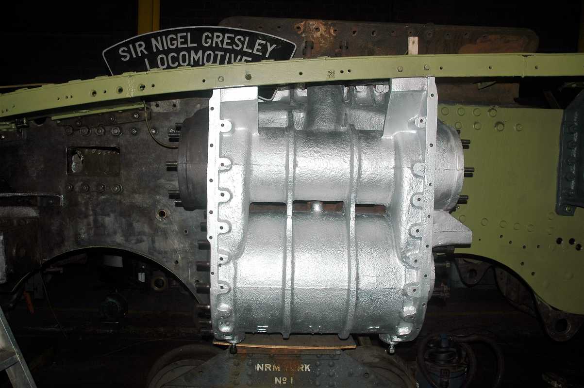
One of the most noticeable changes to the appearance of the loco this week was the silver priming of the outside cylinder castings. It’s certainly eye-catching. The Painting Team continued work around the footplating but also applied gloss top coat to the air pump bracket.
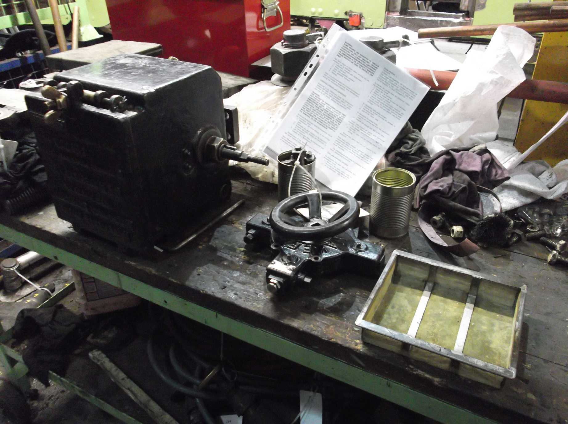
The mechanical lubricators, axlebox and cylinder were returned to the workshop from storage for overhaul. They had been cleaned before storage, but they have required some further attention this week when the ratchet mechanisms were opened as they are packed with grease. Wear to the pawls is evident, which is to be expected. Both sets of pawls will be carefully refurbished to ensure future correct operation.
The dragbox spotfacing continued this week. It was difficult to get a good finish on a couple of the holes, so a single-point cutter was made and did a good job of levelling the spotface on the remaining holes. A spotface cutter-mounted abrasive disc was also made to give them a final polish. The sharp edges of the holes were removed on Friday and we are now ready to fit new bolts.
While priming continues on the footplating we have been removing the remaining loose rivets and welding up bolts in the footplating on the left-hand side. Loose rivets and bolts left in place wear their holes and countersinks meaning when they are removed the holes need work to repair them before we can fit new fasteners. Some have been re-drilled and worn so much over the years that they require welding up and remaking. Some of the holes were welded on Saturday.

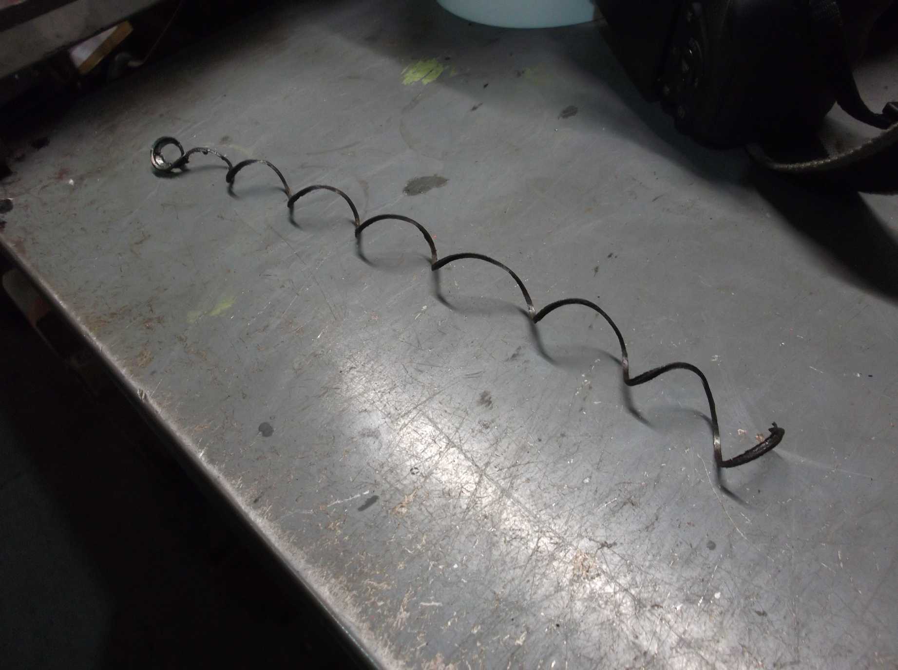
This week, the steam sandbox lids were refitted with new chains. A new eyelet for attaching the chain to the right-hand lid was copied from the remaining one in the left-hand, which looks to be part of the original lid. Also this week a new stud was made for the trailing right brake hanger bracket. The old stud was too short to take a full nut and be pinned, and when removed from the frames the stud was substantially shorter than the other studs used for securing the brackets.
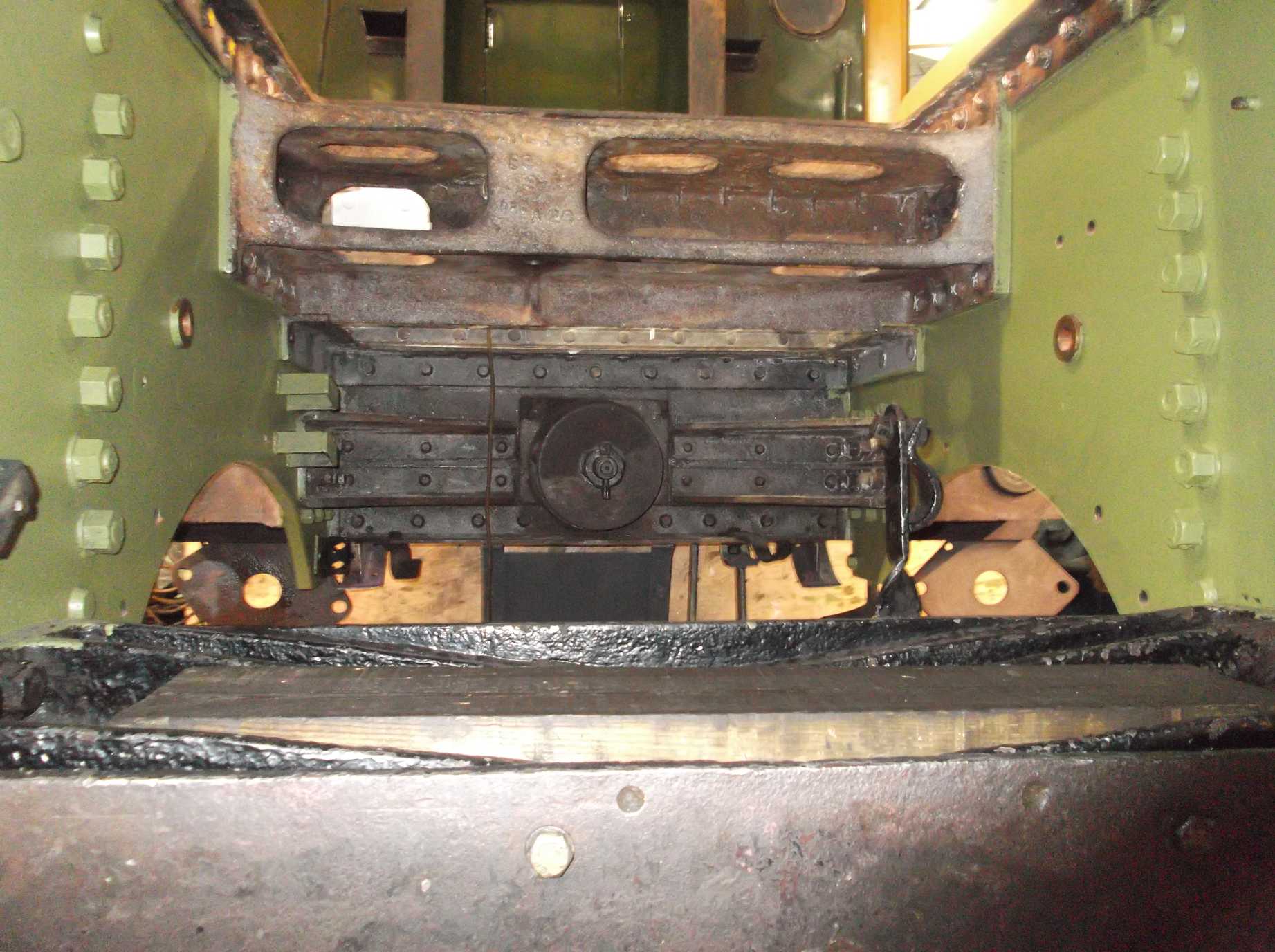
The last sections of mainframes were inspected this week prior to painting. Careful inspection was made around the leading sections of the frames and front bufferbeam, where the loco may suffer from impact damage. No defects were found. Still on the subject of frames the horn castings are being subject to detailed inspection. The inside top corners, where the horn liner lubrication is introduced, was detail-cleaned and the lubrication pipe bushes were removed and the oilways cleaned.
I think a superb job is being done on 60007’s overhaul and thank you for providing these updates.
Good to see the work being done to my favorite loco ,keep up the good work!