Locomotive Engineer Darrin Crone provides us with an insight into recent weeks’ work.
Week commencing 19 September
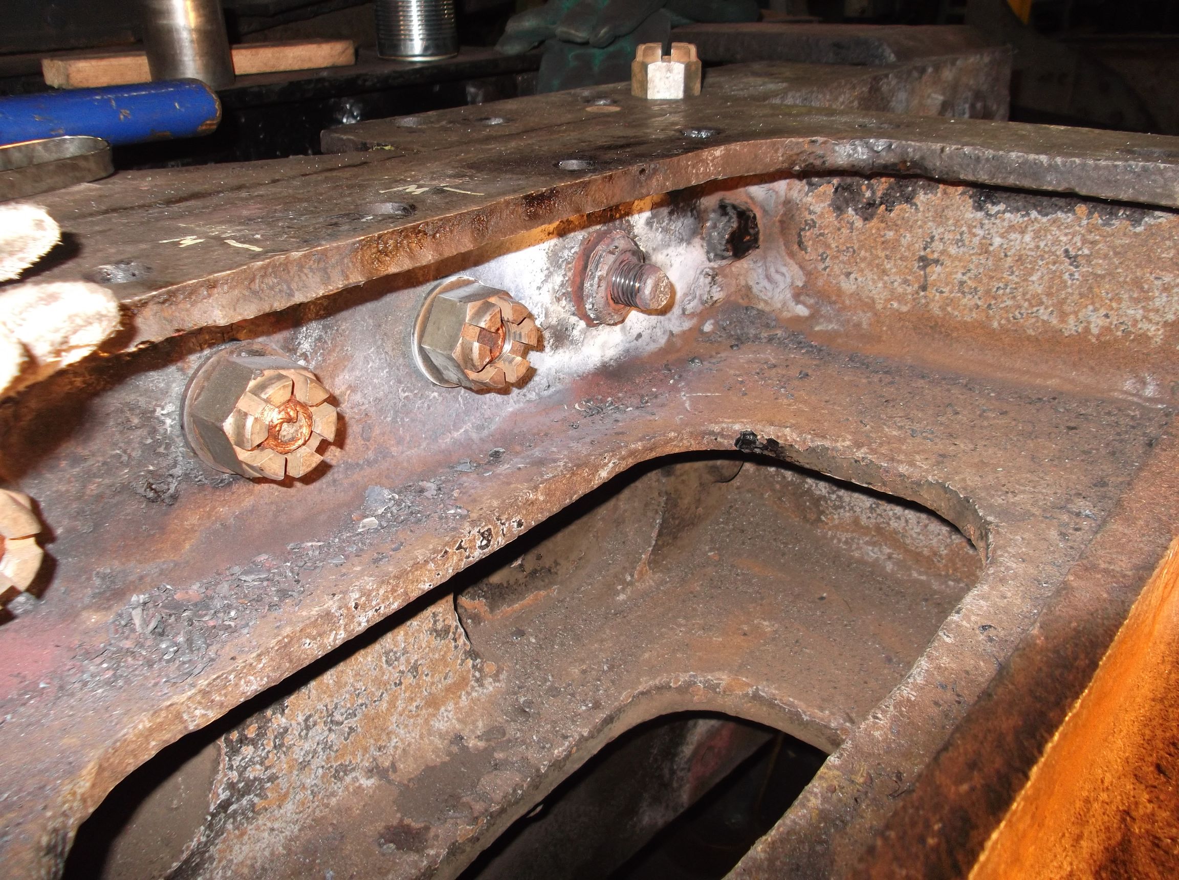
As mentioned in a previous report there’s still plenty of meat in the dragbox but the nuts look a little tired after being covered up in the dark for so long. We were very pleased to find that when the first nut was removed the thread on the bolt looked to be in good condition, and when a die nut had been run down it to clean it up it looked like new. This means that the fitted bolt, still tight in its hole, can be reused with the addition of a new nut. However, three of the bolts had to be removed as the treads showed signs of corrosion. And, as usual with steam locomotives, the three requiring renewal were the most inaccessable.
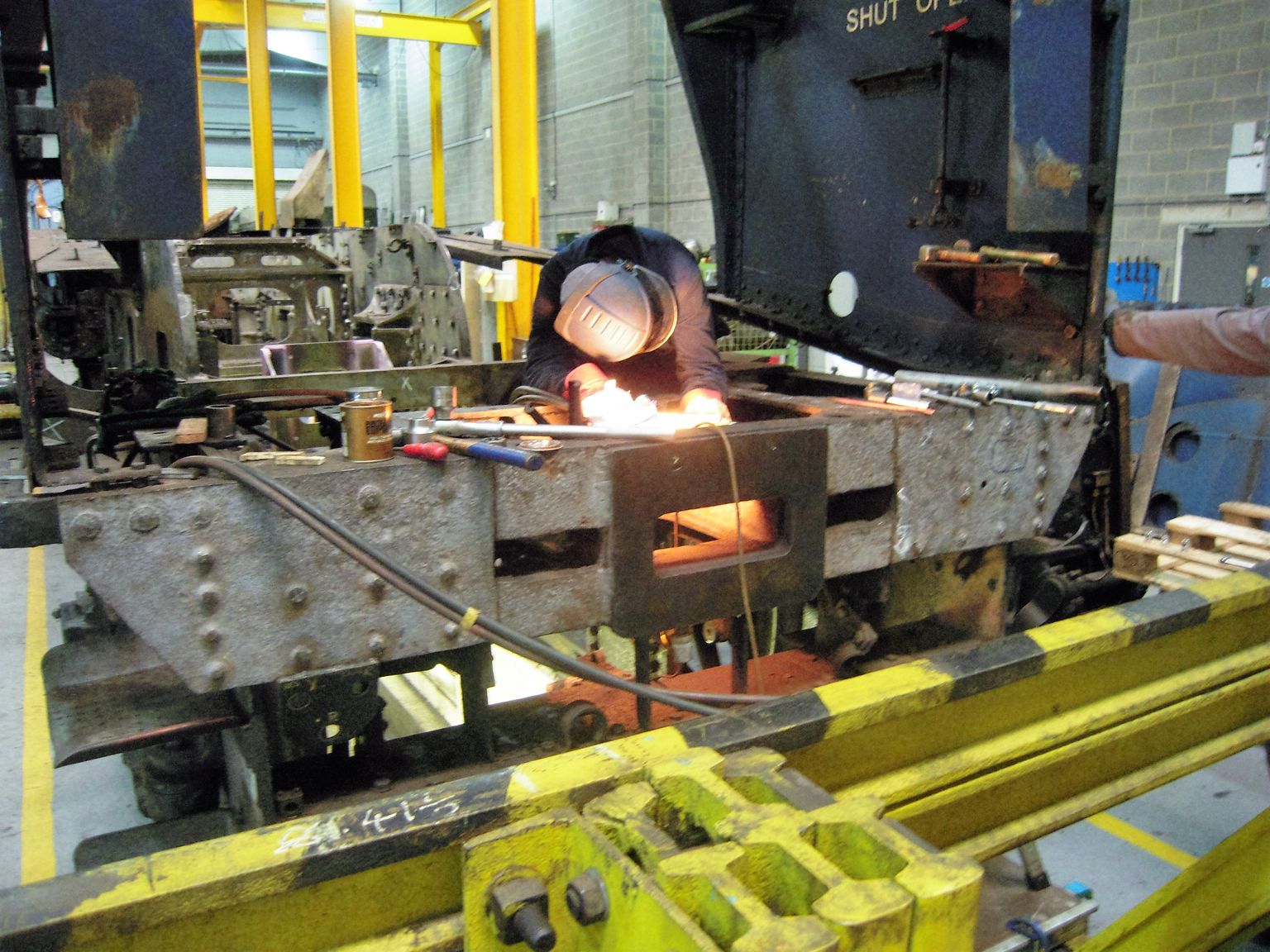
We first attempted to remove them by heating them then allowing them to cool. But they didn’t respond to this so we then drilled down the centres and burnt out as much material as safely possible to avoid any damage to the dragbox casting. By removing material – and with the use of a big hammer – we eventually got them out. There was certainly no danger of the dragbox coming out in traffic if these bolts were anything to go by.
At the front of the locomotive the front coupling hook was removed for inspection and cleaning-out of the piston ring grooves was completed. The dye penetrant testing of the spring hanger brackets was continued this week.
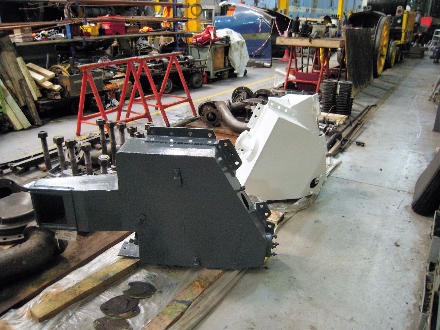
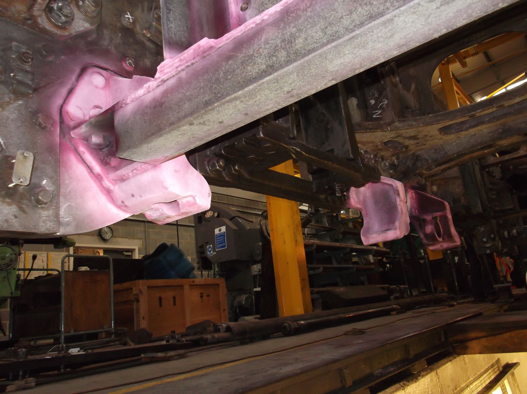
Painting of the the sandboxes and suspension components continued this week, with the first coats of undercoat being applied. We now have green, white and grey painted parts. It’s confusing to me, but the Painting Team know exactly where they are up to.
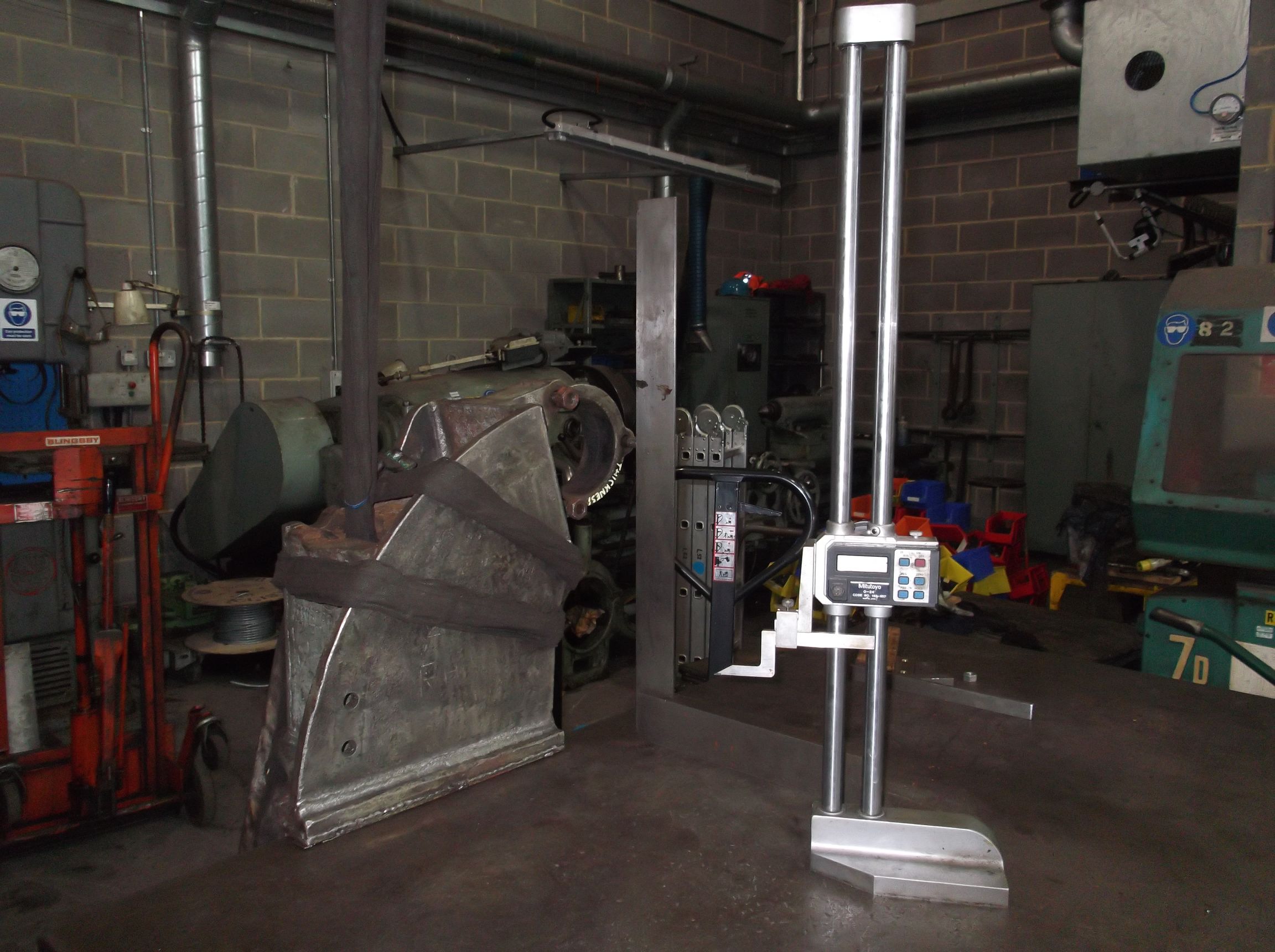
The combined spring and brake shaft brackets have now been measured and compared to drawing. The removed right hand bracket was lifted onto the marking out table so that we could measure it accurately. As this bracket is to be repaired it will be modified to match the left bracket that is still on the loco.
The decarboning of the exhaust passages continued this week. On Friday the Engineering Team were still pulling out lumps so there’s still work to do in here.
Week commencing 26 September
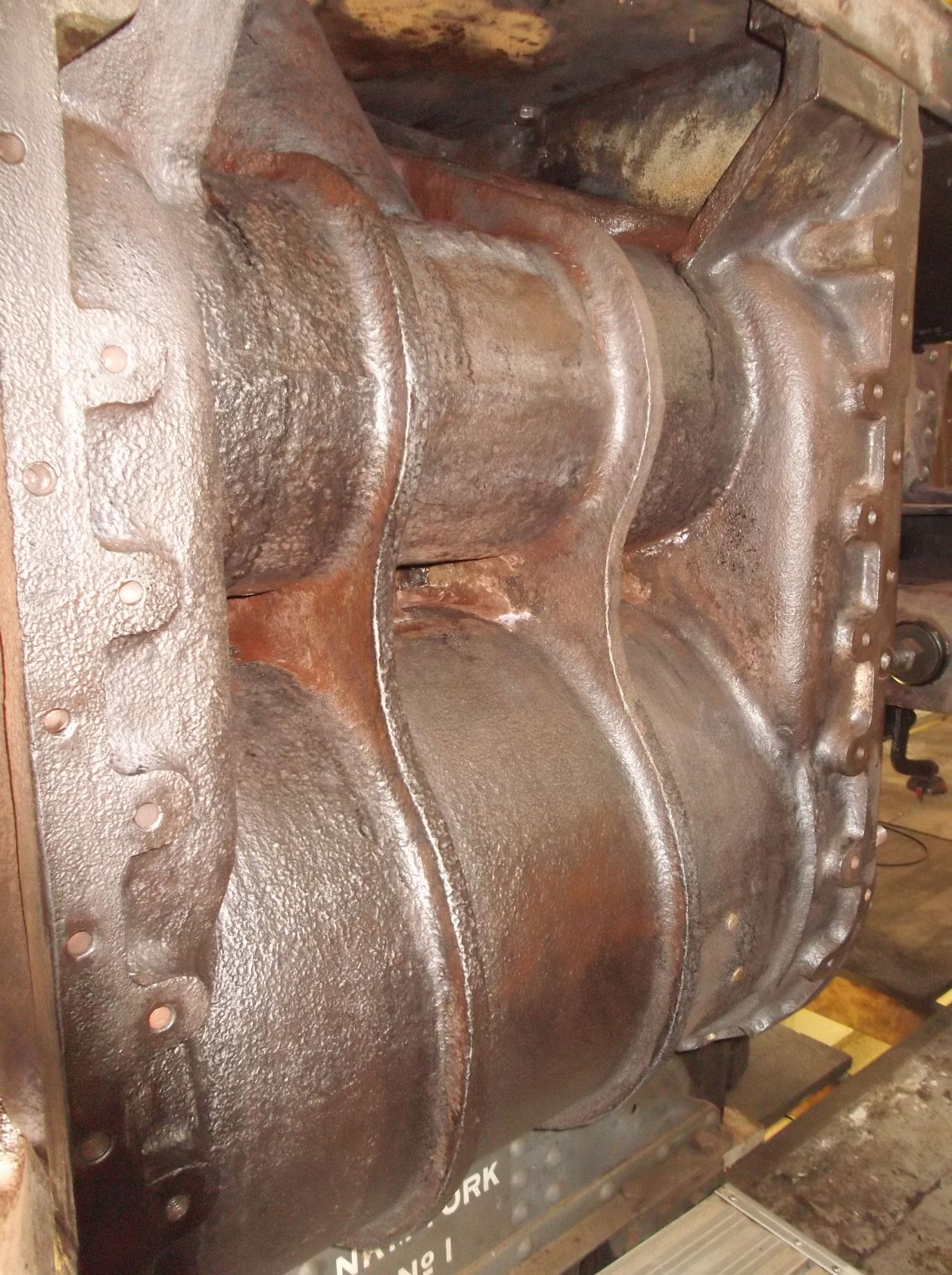
Now that the frames have been completely stripped, attention is focusing on the cylinders, saddle and the front bufferbeam. The cast surfaces of the cylinders and saddle need a few coats of the needle gun to really get down to sound material. Much of the cylinder casting surface area is not accessible to the needle gun, so we have to use other tools: powered tools like the wire brush, and hand tools including long chisels and scrapers.
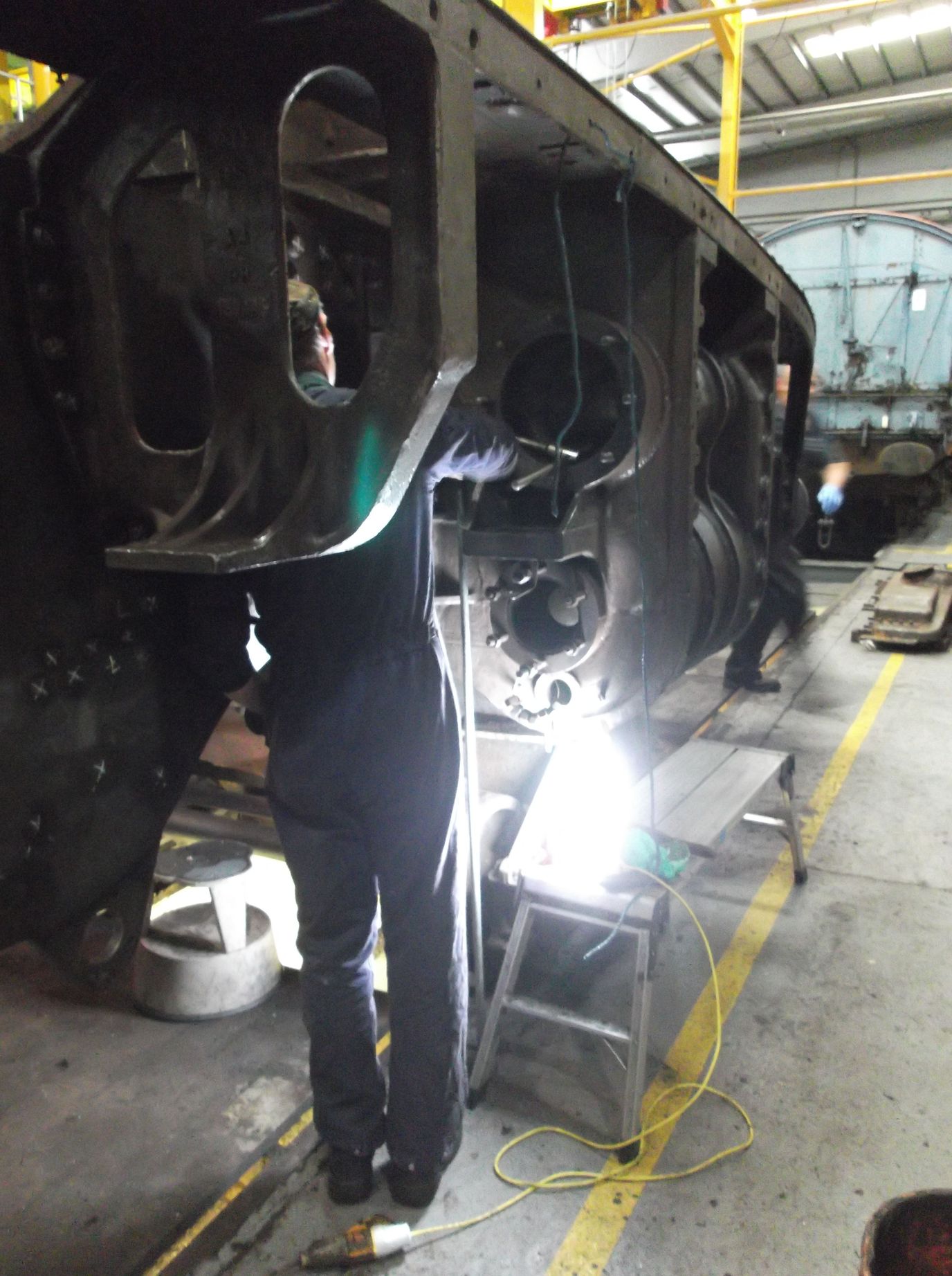
We have also started to decarbon the exhaust passages – good progress has been made using a piece of pipe, the business end of which has been cut at an angle. With this tool we can reach well up into the passages, beyond the reach of an arm and a scraper. It has the added advantage of enabling us to see what we’re doing.
Toward the front of the loco the coupling shackle has been removed and the bufferbeam and coupling housing have been needle gunned. These will be removed for inspection shortly.
The broken stud removal around the cylinders was completed this week, though I think I may have found another broken stud. Removal of the wasted leading sandbox mounting studs has also been commenced. All have been removed from the right-hand side.
The meticulous degreasing of the upturned bogie was continued this week. The leading hornstays were removed and cleaned together with the mating surfaces on the bogie prior to the refitting of the hornstays.
The inspection of the frames continued this week, with our CME checking the defects that have been identified so far. No nasty surprises, just the amount of wear and tear that can reasonably be expected after ten years of hard work, a few loose rivets and fitted bolts to remove and replace with new ones. Of course, some are in the most inaccessible places, so if anybody is good at holding a hand drill or grinder above their heads for extended periods let me know.
On Thursday the Engineering Team began dye-penetrant inspection of the spring hanger brackets. The welds around the air pump bracket were also tested and no defects were found.
While our CME was on site he continued his measuring of the cylinder bores by examining the left hand side.
This is the eighth update on the restoration of Sir Nigel Gresley – you can catch up on the previous posts here.
Delighted to see Sir Nigel Gresley will be back to best bib and tucker.
I sometimes wonder about swapping the name plate from the Duchess of Hamilton to that of
Sir William A. Stanier FRS.
Two fine genetleman could stand together.
When you say >>>>We first attempted to remove them (dragbox nuts) by heating them then allowing them to cool. But they didn’t respond to this <<<<<<
are you sure this is what happened? or was the nuts attempted removal when they were still hot? …..because steel when heated red hot and allowed to cool down.. will have slightly shrunk when cold and the nuts may be tighter than original…unless the threads are very rusty the heat may destroy the rust and they may come undone …but it is best to heat the nut as fast as possible as the bolt has less time to heat up ..we dont want the bolt to expand…and undo the nut as fast as possible…preferably with impact gun