Locomotive Engineer Darrin Crone provides us with an insight into recent weeks’ work on restoring the great locomotive.
Week commencing 3 February
All the footplate rivet holes have now been repaired and are ready for new rivets to be fitted, except one. The one outstanding hole is in the corner of a bracket which, though detailed as riveted on the LNER drawing, is impossible to get a rivet of sufficient length in. The hole had a bolt in it welded to the footplate which was clearly not original. So it’s a mystery how the LNER did it. The repaired holes have been drilled and countersunk back to the size detailed on the original LNER drawings.
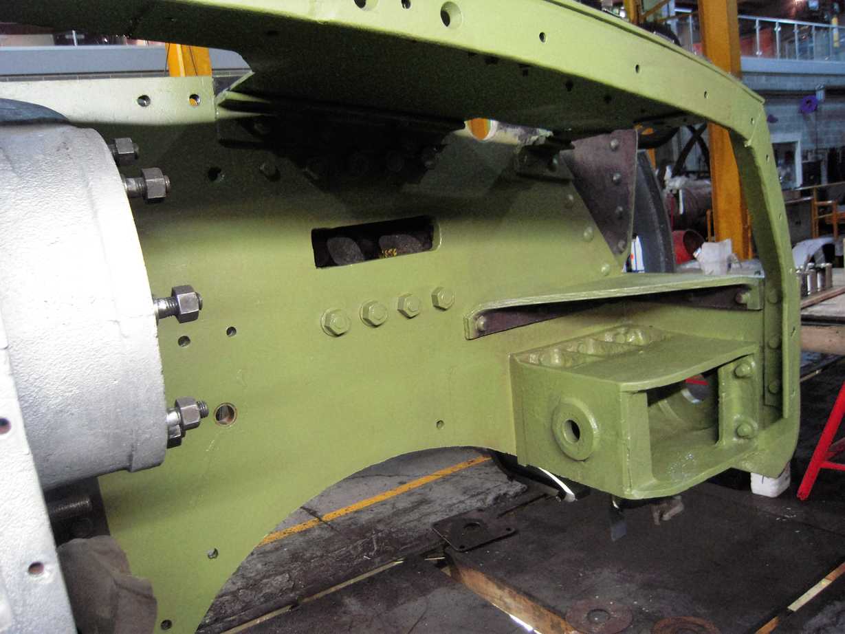
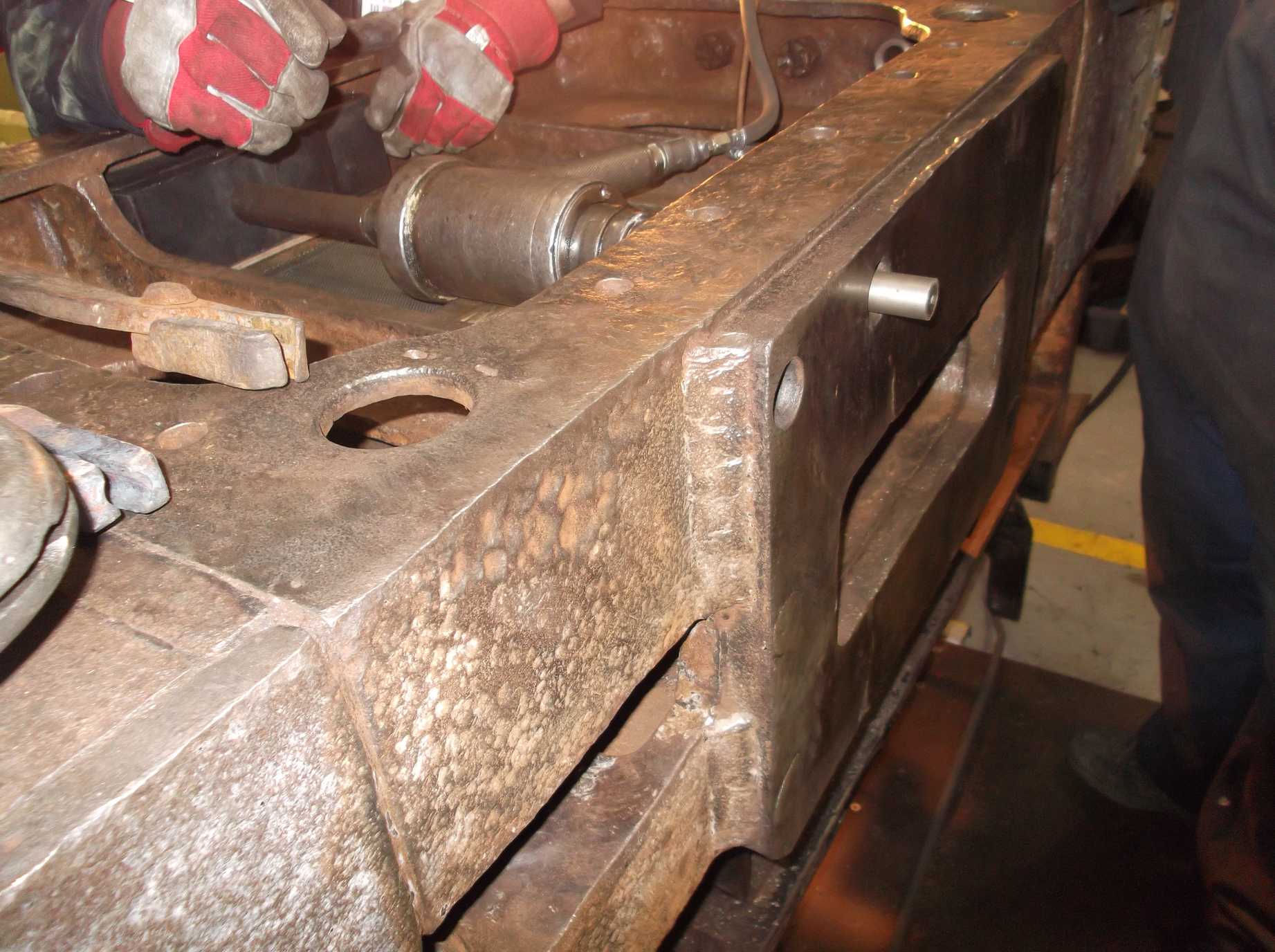
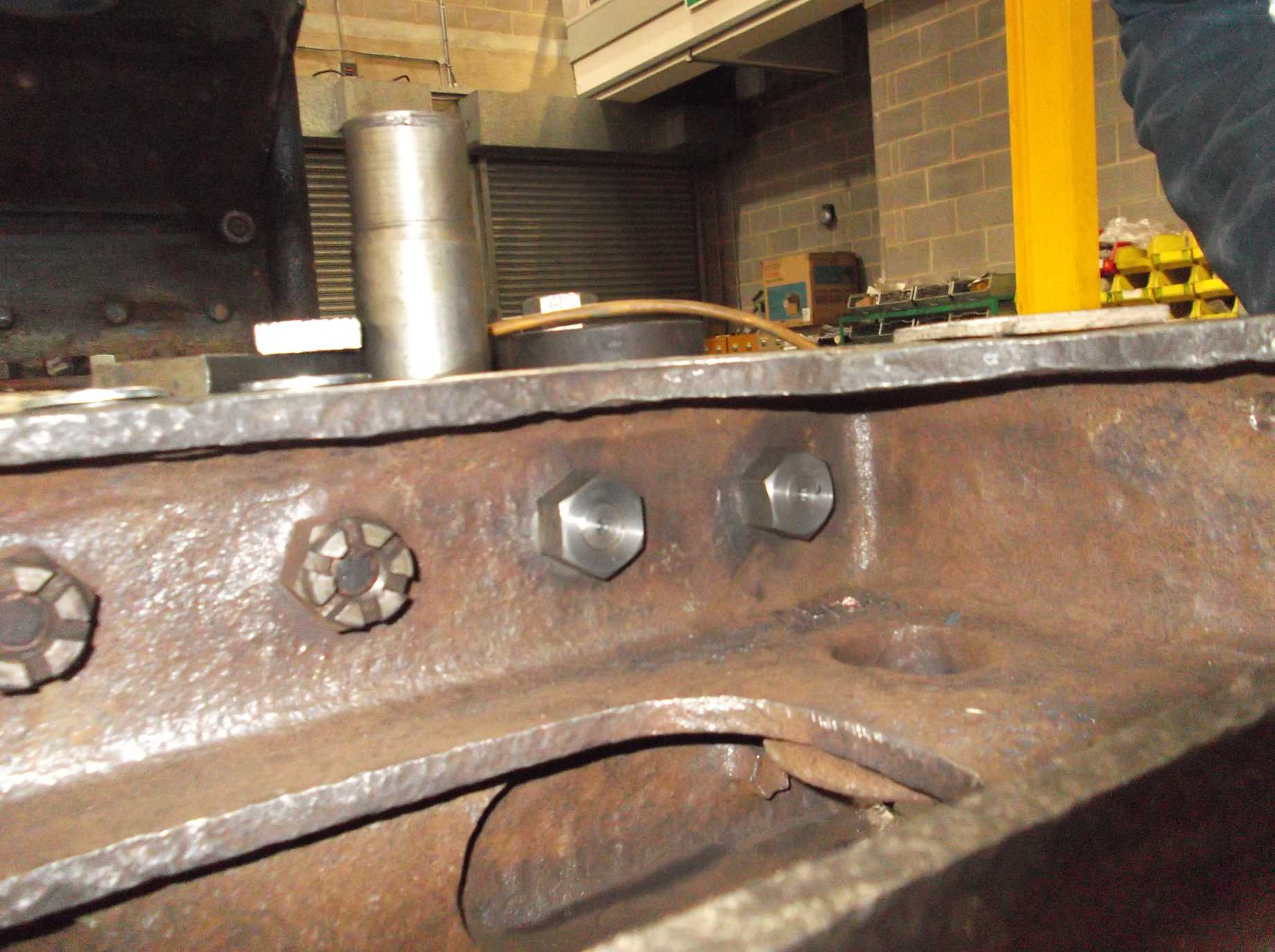
We are now ready to fit new bolts to the dragbox and new nuts to the existing bolts. Suitable washers to match the full-size Whitworth nuts were finally delivered this week, too late to be fitted. In preparation, the top of the dragbox was cleaned and the needlegun used to remove scale from around where the new nuts will be fitted.
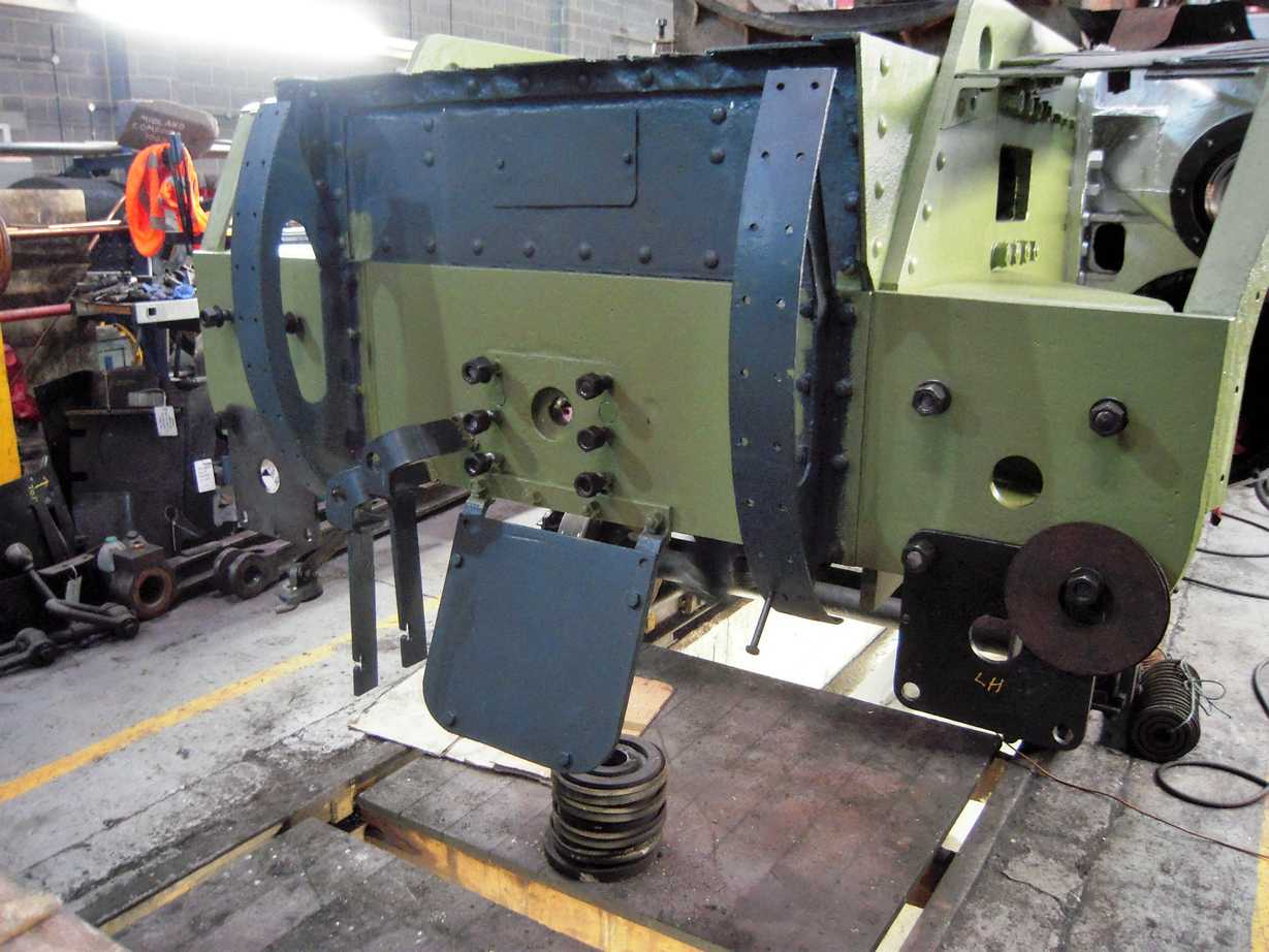
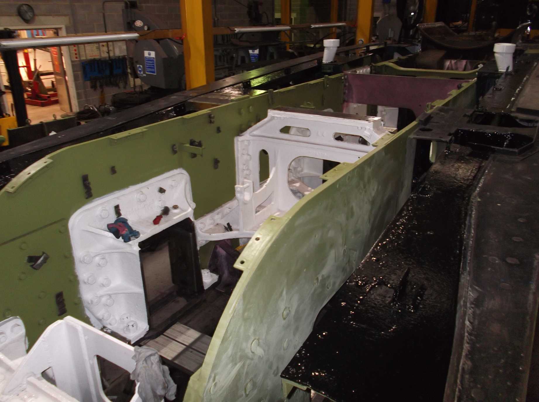
Painting continues with the frames in front of the cylinders on the outside being primed. The Paint Team have also painted the front bufferbeam. The front coupling hook housing was removed again this week and was painted. The housing shows wear, which is to be expected. This will have to be measured to examine if the wear is acceptable or requires repair.
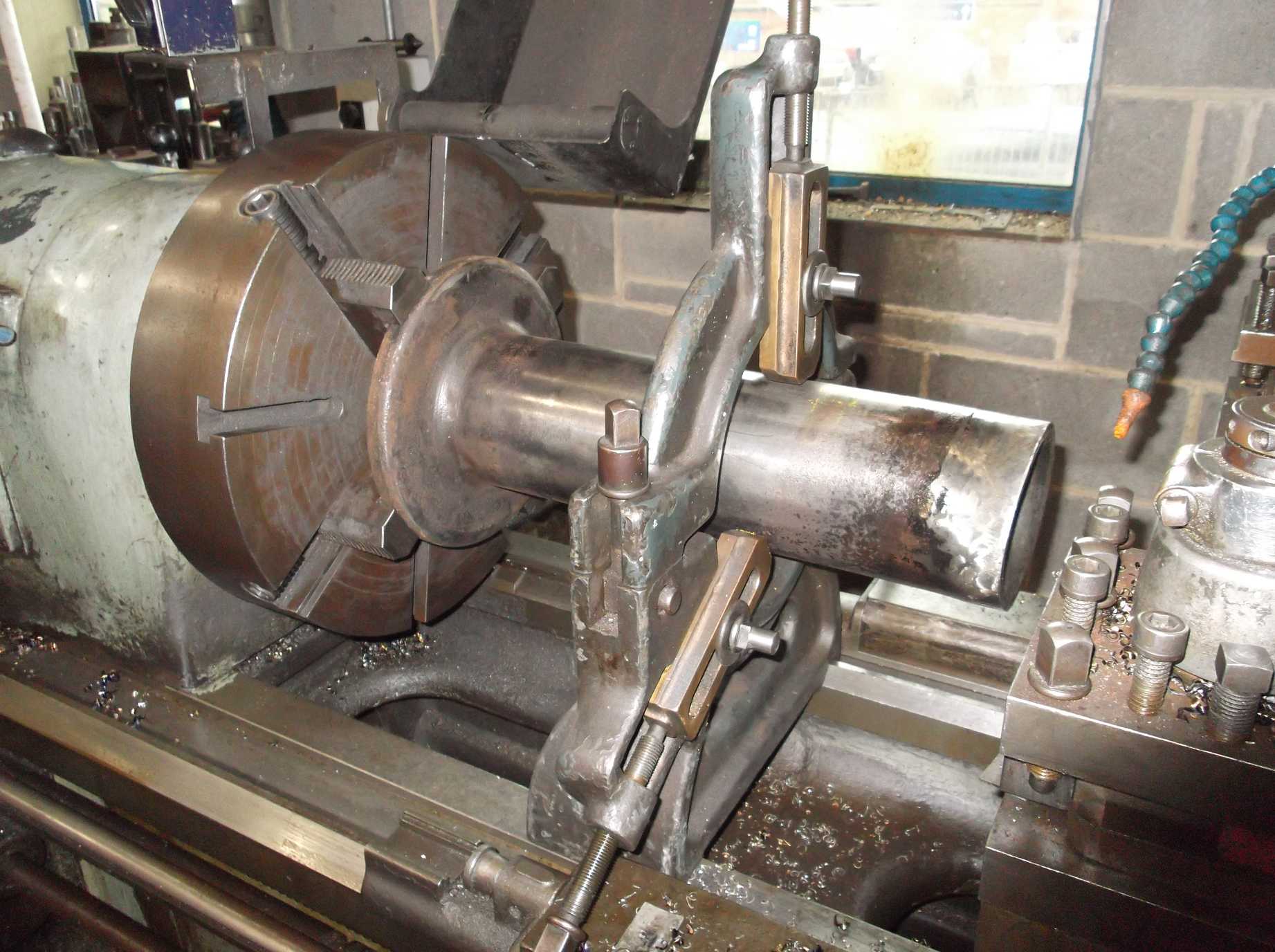
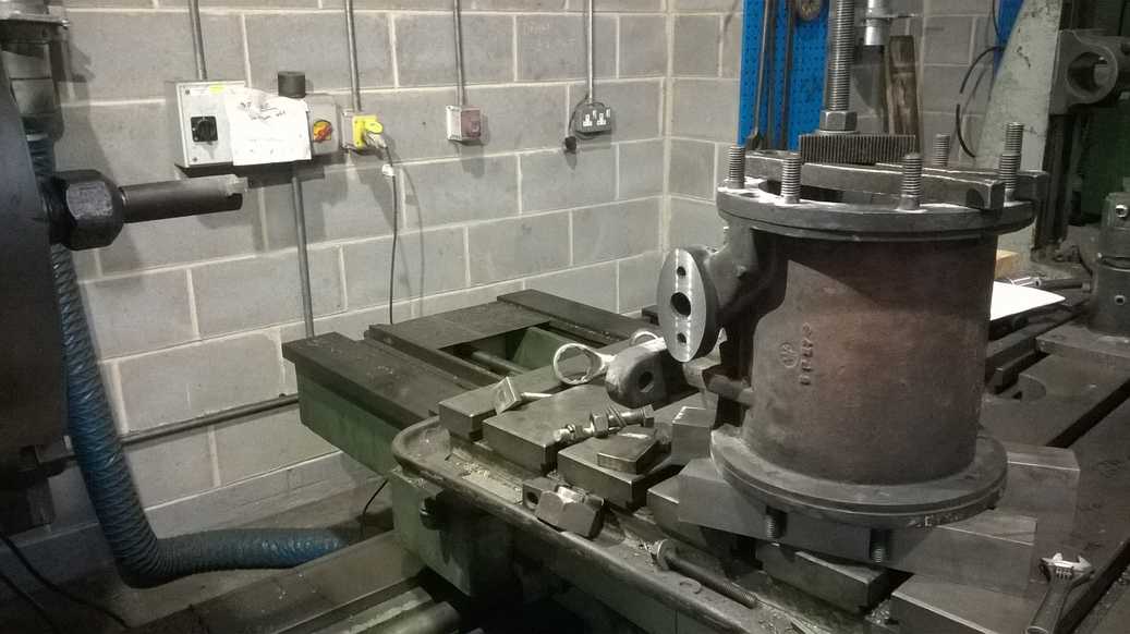
The inner sleeves of the front buffers are now being examined and refurbished to remove the decades of wear they show. The first one was put in the lathe to check for straightness and its front section was carefully skimmed to remove surface marks and impact damage.
The exhaust silencer for the air pump was inspected then primed this week. The drain valve on the bottom of the silencer was stripped, cleaned out and examined. On the subject of examination, 5 of the 6 coupled wheel horn castings were inspected. The painters will be pleased to know that these can now receive their attention.
The splasher bracket rivet holes in the frames were finished and countersunk with a special tool made by the Engineering Team. It worked very well and the finish of the holes is now suitable for the fitting of countersunk rivets. The rivets will have larger-than-normal countersunk heads so have to be specially made. The longer rivets for the brackets, which are attached to the double frames, were made on Saturday.
The middle cylinder cover holes received a final clean out this week, now that all the studs have been removed. They have all been inspected and are in good enough condition for new studs to be fitted.
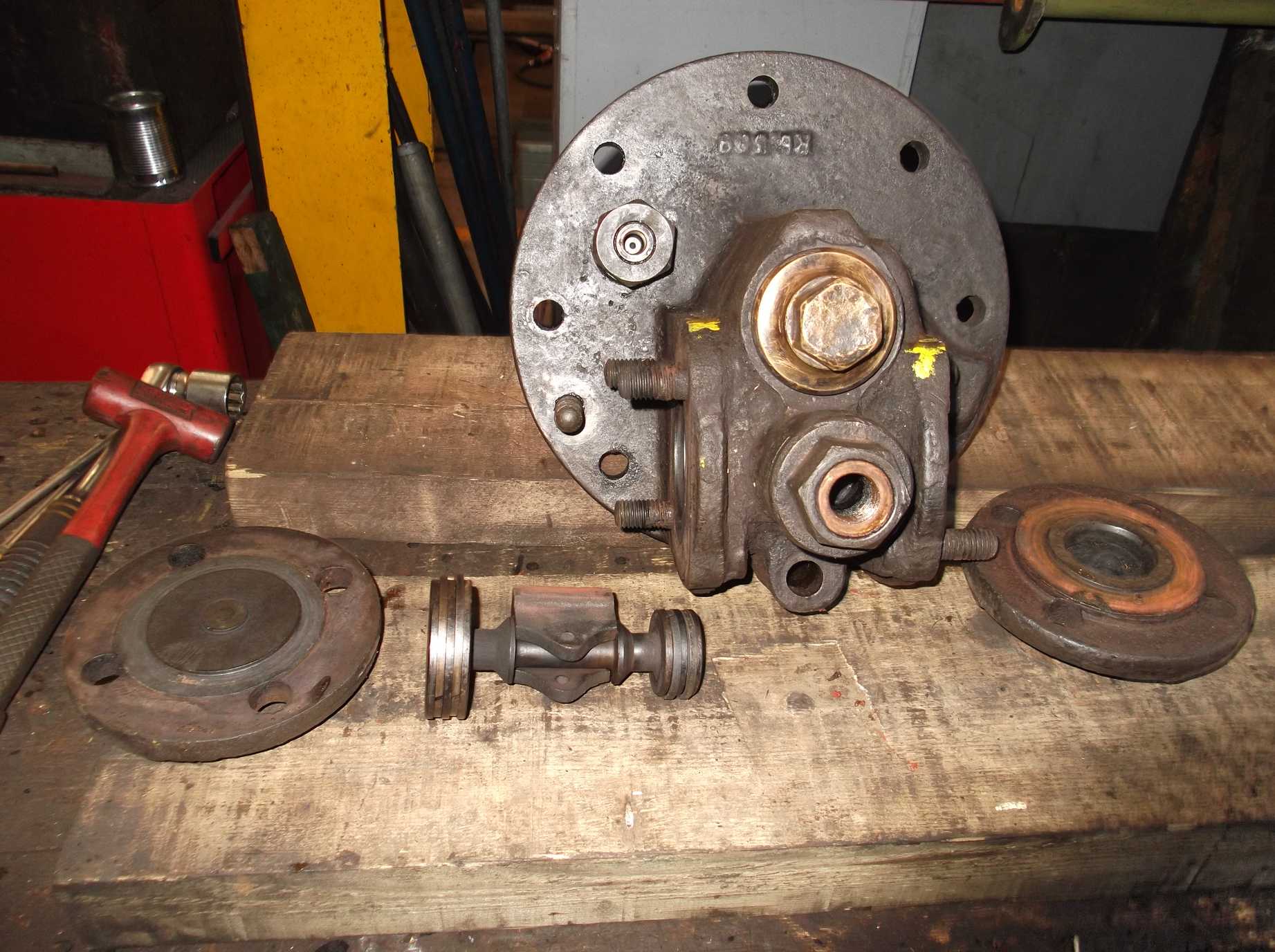
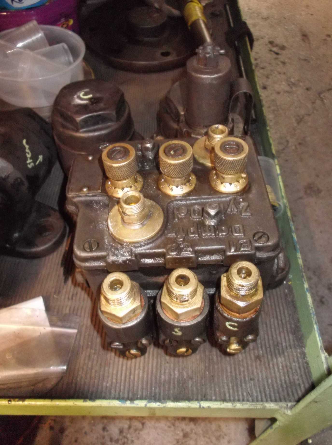
The overhaul of the air pump began this week, after extensive cleaning over previous weeks. Engineering Team volunteers have done a great job in information gathering and we have photographs from the last overhaul. This week it was decided that we must first find a spot in the workshop where we can dismantle the pump and lay out its parts without them being disturbed, so an area was identified and agreed with the workshop management. The area will be cleared and the air pump moved.
Week commencing 10 February
The right-hand buffer sleeve put in the lathe last week has now been finished. With an impressive result, the left-hand sleeve was similarly treated. The surface skimming also involved restoring the internal radii that matches the back of the buffer head. After taking a couple of photos, the ends have been taped up to protect them until they are refitted to the loco. We must thank Dan Holmes of the National Railway Museum for allowing us to put the sleeves on his treasured Holbrook lathe and operating the hydraulic copier to ensure accurate machining of the end radii. The buffer housings have backing plates that are screwed onto the housings. The threads on the housings have either been re-tapped oversize or have broken screws in the holes. This week the repair of the holes was started, with the welding up of the oversize holes so they can be re-drilled and tapped.

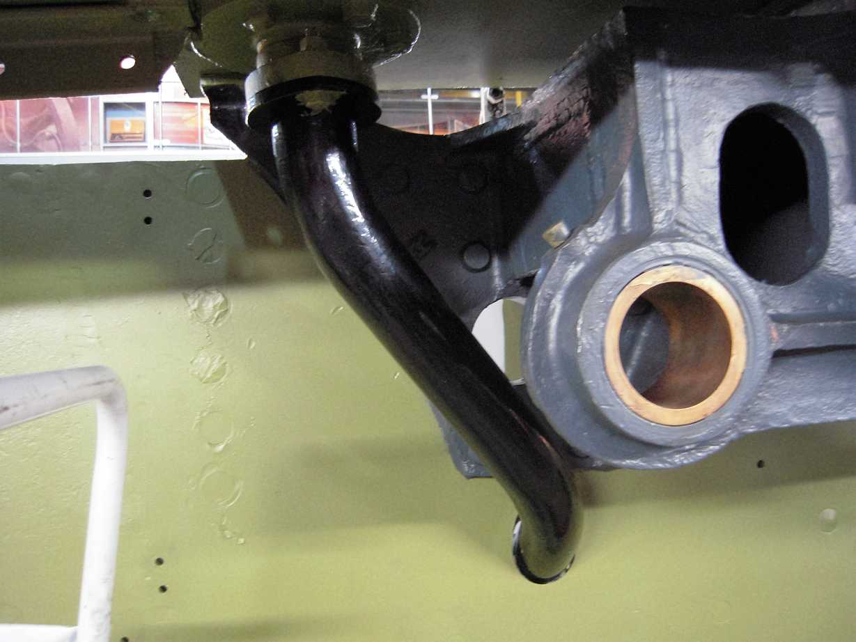
The refitting of the steam sands filler pipes was completed this week. Like many parts around the engine, they have been examined and repainted off the loco. Particular care was taken to ensure that water can’t get into the sandboxes, so new seals and packings have been fitted. Fitting also ensured that there is clearance around the pipes where they go through the frames to ensure no chafing in traffic. Very elegant they look, too; much better than on another Gresley Pacific we have recently shared workshop space with, which has angular looking fabricated pipes.
The air pump overhaul began in earnest this week with the air pump being moved on to a bench where dismantling and examination began. Preliminary examination shows little apparent wear to the cylinder bores, but it is early days yet.

The countersunk rivets – for which we need to finish the riveting of the splasher frame brackets – were made this week. The long ones for the double frames were machined last week.
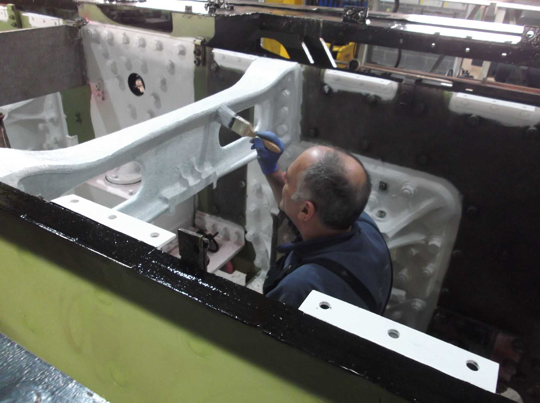
The saddle casting was signed off last week by our Chief Mechanical Engineer (CME), subject to some minor repair work. This allowed the painting team to work on it. After a brief visit by the needle gun a coat of high-temperature silver was applied. The rear flange of the saddle has been left unpainted as there are numerous holes from fastening down the smokebox, not all used, so they will be welded up and re-drilled after the refitting of the boiler.
Meanwhile in the dragbox, descaling has continued. Originally planned to be a final descale around the existing bolts to ensure a good base for the fitting of new nuts, the results have been so good that it has been extended to the entire dragbox casting. It is worth doing as the cleaner we can get it and then get it painted the longer it will last. The good surface finish will also now allow a more reliable di-pen examination.
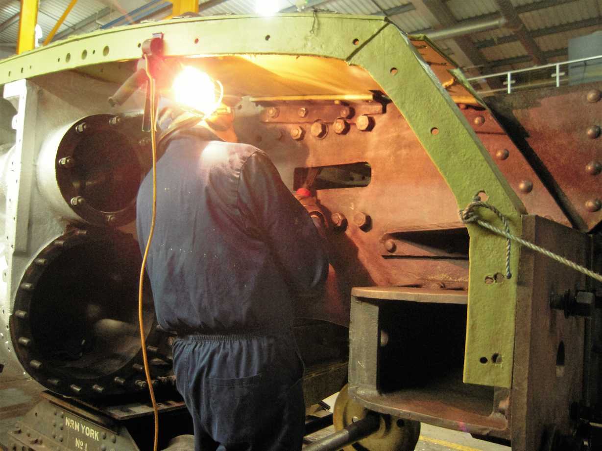
The horn castings have now all been examined and di-pen tested with the last one completed on Tuesday. The painting team were straight on to the castings and they have now all been primed. Painting continued between the frames this week. On Saturday the repaired leading right hornstay returned to York and was refitted by our junior volunteers, the ‘007 Gang’, under the guidance of our CME. With this refitted, the leading left was then removed for repair.
Week commencing 17 February
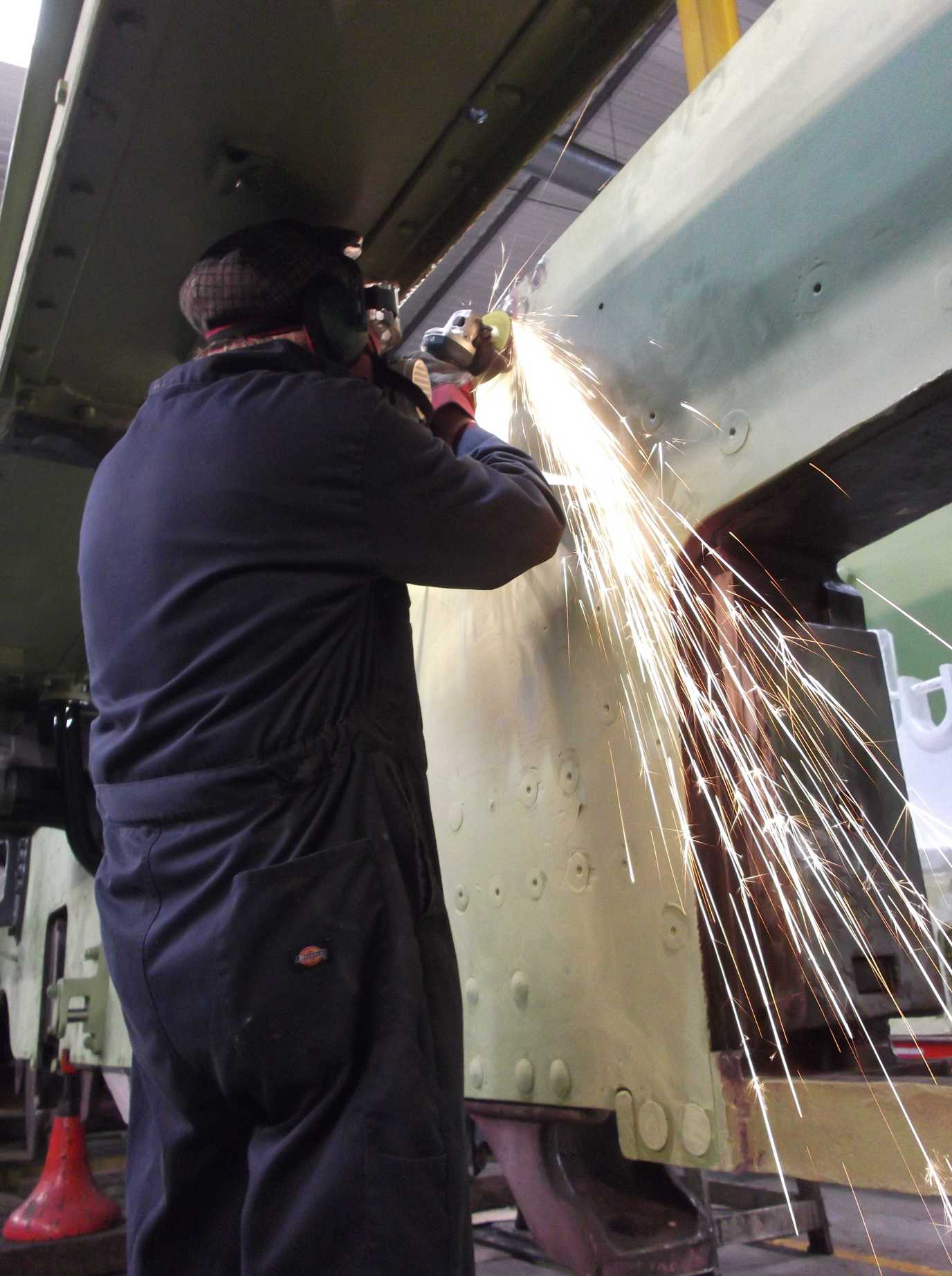
Painting of the frames continued with, by the end of the week, the primed outside frames receiving a rub down prior to their first coat of undercoat. Work has also concentrated on finishing the footplating in preparation for the refitting of the splashers.
The buffer housing threads to secure the backplates have now been repaired and the plates have been fastened on with countersunk screws, as originally fitted.
The tender was worked on this week as the refurbishment of the loco dragbox job also includes the inspection of the intermediate draw bar and safety links. However, due to the location of the tender in the workshop we are unable to do much, but it is expected to shunt the tender in to a better location in the next couple of weeks. A start was made cleaning out the dragbox on the tender front.
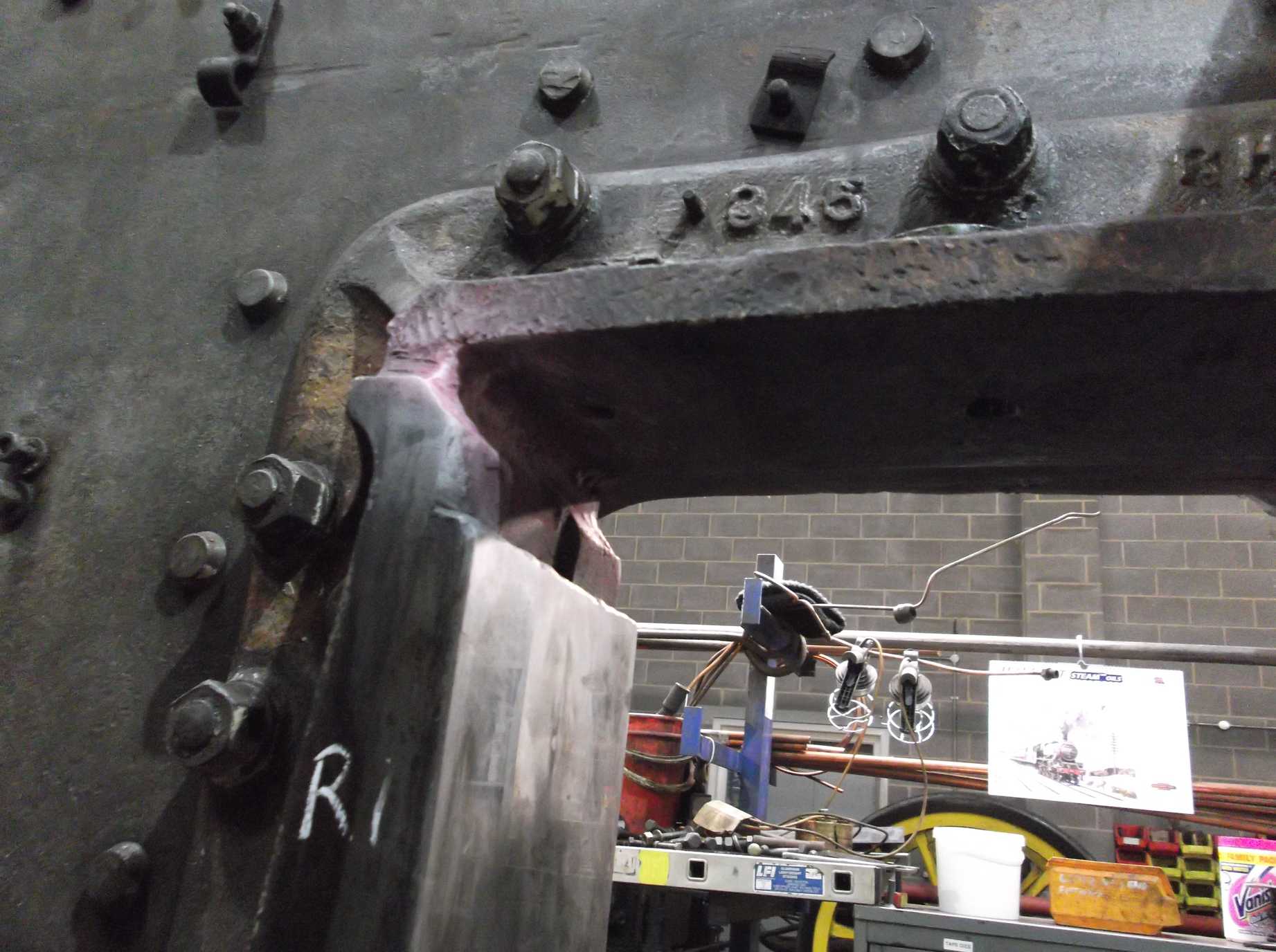
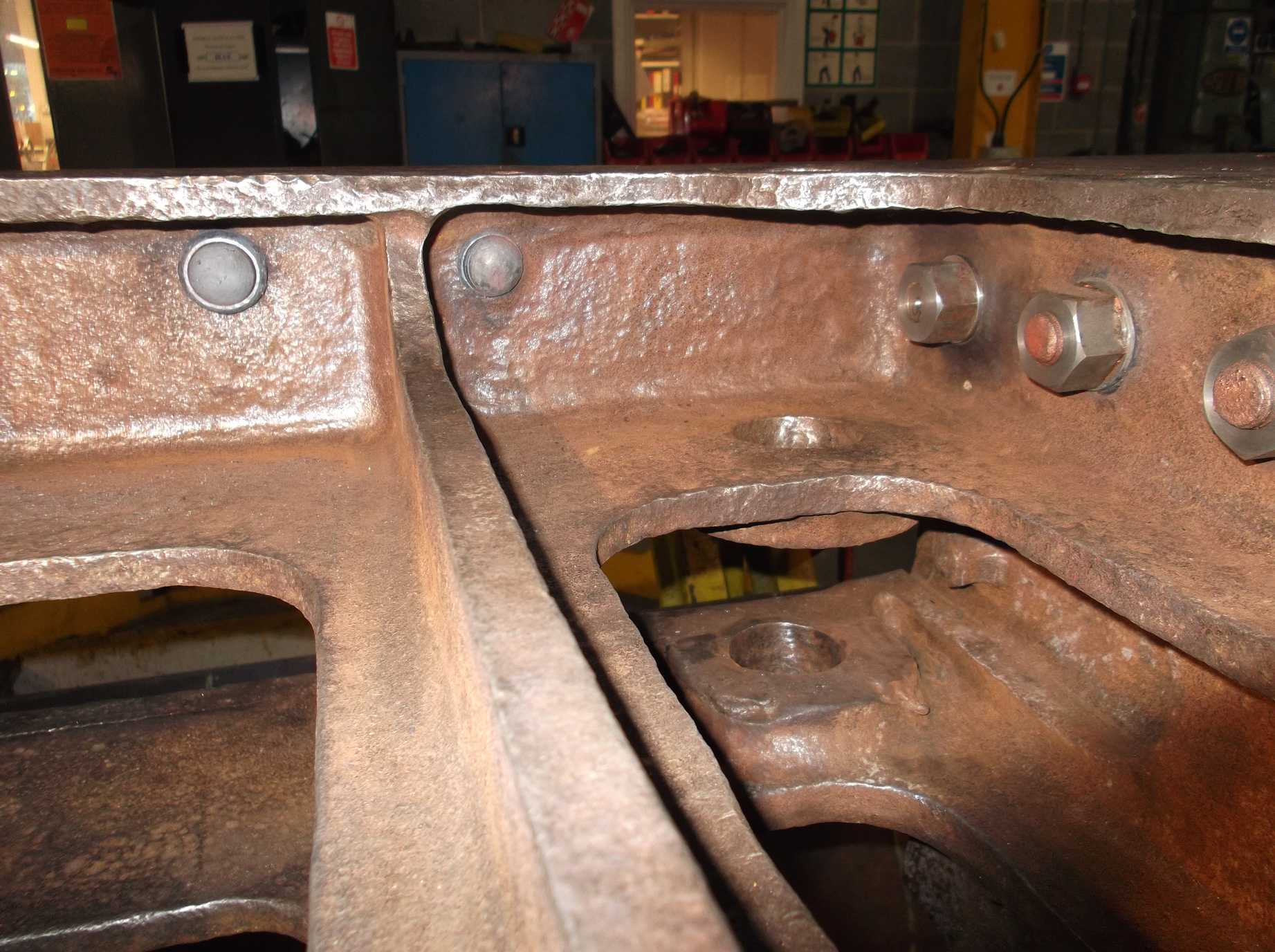
We have previously had sessions of riveting the splasher brackets to the frame tops, however some rivets could not be put in due to the inaccessibility of some of the holes. We borrowed a compact hydraulic rivet squeezer but unfortunately it lacked the power we needed, so we decided to attack the problem from the opposite side of the frames.
The original arrangement was for rivets to be held up from the inside of the frames and closed or hammered down from the outside. Holding up from the outside meant using countersunk rivets, however the countersinks on the outside of the frames were in poor condition so using this side meant first repairing the countersinks. A special countersink had to be manufactured to give us the correct form and this was used successfully a couple of weeks ago.
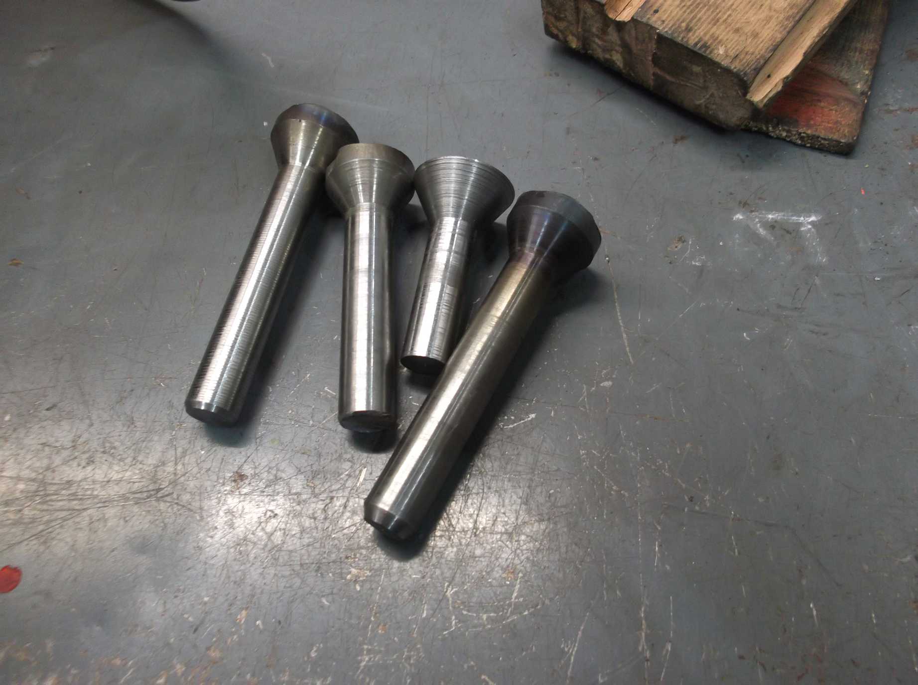
Next, we needed rivets, but standard form countersunk rivets did not have heads big enough to fill the countersink and allow them to be held with the equipment we have. So, special rivets were made from the same material our rivet manufacturer uses. As the clearance we have is small, a special attachment had to be made to go in the equipment we use to hold the rivet head in place. This perhaps gives you some idea of what is involved behind the simple statement that we have riveted the splasher brackets back on.
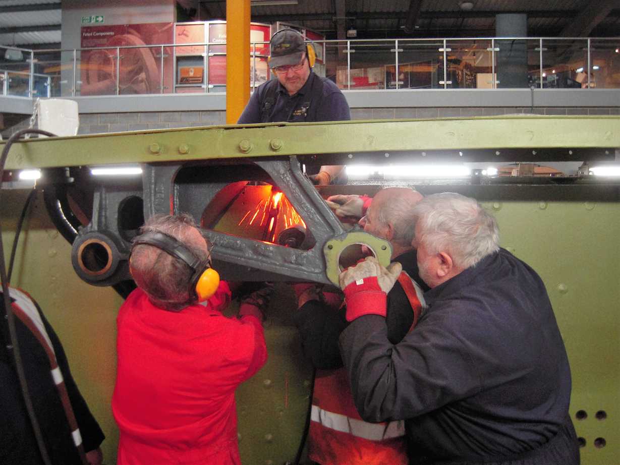
The riveting team was assembled on Wednesday. The team required 5 people, this may be a surprisingly large number but we had one on the torch heating the rivet, someone on the tongs to move the rivet to the hole, another to knock the rivet in the hole allowing the tongs to get out of the way, someone to put the jamback in place to squeeze the rivet head in to the hole and finally the riveter to close the rivet with the hammer.
While riveting the splasher brackets on Wednesday we also replaced 2 rivets in the dragbox. One was 3/4″ and one 7/8″, which closed up very easily, a relief after the time it takes for setting up. We must thank the riveter for allowing us to use his riveting equipment and also for his foresight in saving it from the scrap man once the shipyards on Teesside ended riveting.
The countersunk side of the rivets, splasher and dragbox, were finally ground flush. The splasher brackets were cleaned and then given their first coat of primer.
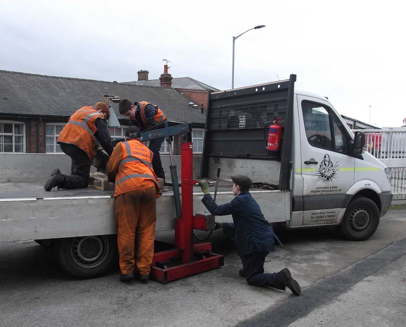
The left leading hornstay returned to York on Saturday after repair and was refitted. The hornstay was returned by the repairers transport so as a return load the leading-right combined brake and spring bracket was put on the van for taking to Teesside for refurbishment.
After the hornstay was replaced the frame jacks were repositioned under the centre of the frames.

The coupled wheel tyres are currently being turned and our repairer was planning to light the hearth for heating the first tyre by the end of last week. As reported previously, the bogie wheels have already been re-tyred.
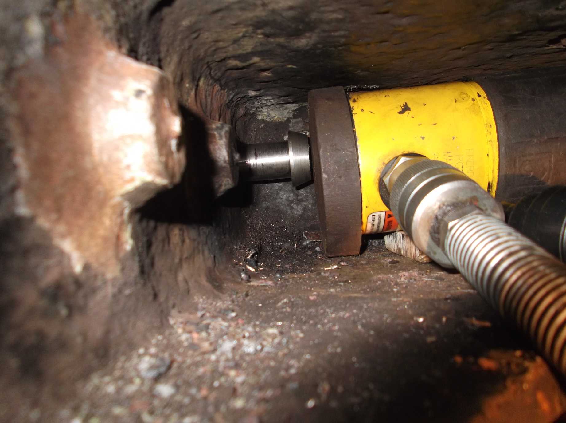
The dragbox has received more descaling this week, with only the bottom underside now requiring finishing off. As the top is finished the first two fitted bolts were put in this week. The holes were accurately measured and the bolts made to give the correct fit. Because of their inaccessibility they couldn’t be knocked in so had to be jacked.
As the bolts are long and the jacks have short strokes it takes a long time to set up, jack the bolt and then insert more packing and start to jack the bolt again. A middle slidebar stretcher fitted bolt identified as requiring replacement during the frame survey was removed for replacement this week and reaming of the hole began.

Week commencing 24 February
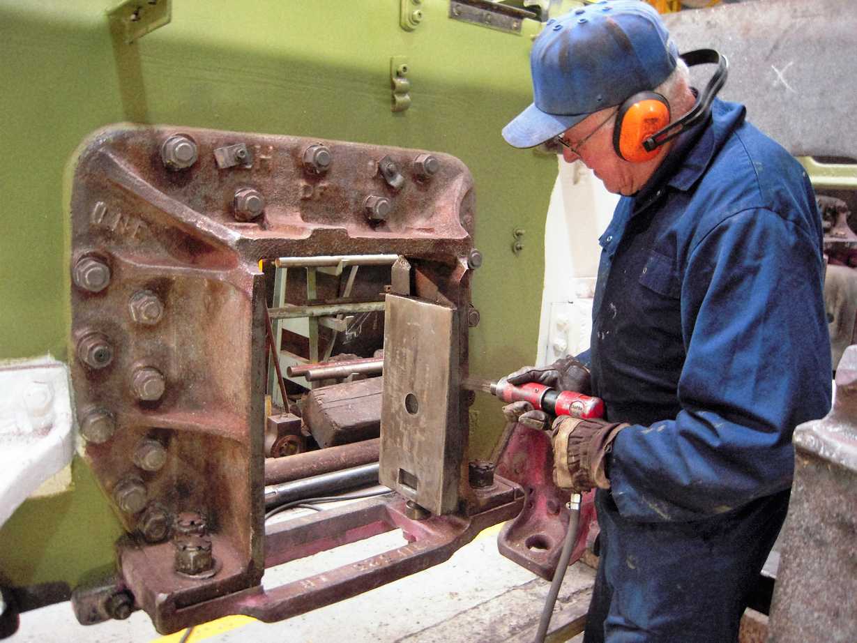
I visited the works where the combined brake shaft and spring hanger bracket is to be refurbished. We have produced a drawing showing the dimensions we need to match the position of the corresponding bracket on the other side of the loco, ensuring that the brake shaft crosses the frames squarely and at the correct height. During the week, the section of the bracket that mates with the loco frames was removed and replaced with new material. By the end of the week the bracket was placed on a boring machine in preparation for machining.

The air pump overhaul continued, with NDT inspection of the piston rod and the three cylinder castings. The steam supply flange on the steam cylinder casting was found to be in poor condition with pitting across its face so it was put on the National Railway Museum’s borer and the face skimmed. As a result of the inspection it has been found that the steam cylinder will require further repair work.

The tops of the frames and splasher brackets are now finish-painted by the volunteer Painting Team. The middle cylinder front and under the saddle has also been prepared so that high-temp silver can be applied. The 2-to-1 lever stretcher was di-penned this week after some needle-gunning in some of the hard to reach corners. No defects were found and it has now been given a coat of primer. On Friday, the front bufferbeam area received a coat of top coat black gloss.
The bogie axleboxes are now subject to detailed measurement and inspection. As the bogie wheels have been re-tyred the final sizes of the journals will soon be known and the bogie boxes can be made to suit.
Under the saddle casting we are replacing a number of worn-out fitted bolts that go through the frames and cylinder flanges. Due to the restricted space and to ensure correct alignment of the repaired holes we decided to start the holes by boring them before final finishing with a reamer. So we have devised a boring jig which was trialled on Thursday. The method we have devised was proved with a hole bored in the saddle casting on the centre of the hole in the cylinder flange. This will ensure a finished hole with a centre line through the saddle, frames and cylinder flange truly perpendicular with the loco frames with the minimum amount of material removed.
In front of the 2-to-1 lever stretcher there are two angle brackets that at some time were cut through, presumably to remove the front plating above the front bufferbeam. We are guessing but it may have been during straightening out the front of the loco after a prang. The rough cuts in the brackets were welded back up equally roughly from underneath, so presumably the footplating in front of the smokebox was left in place. As we can get to the top of the angles these were welded, and also a crack in the left-hand bracket found during the inspection of the 2-to-1 stretcher.
The studs that hold the front buffers on are designed to bottom-out on the castings behind the bufferbeam, This allows undue stress to be put on these castings when tightening the nuts on the studs when fitting the buffers, so the studs have now been shortened so that they correctly stop at the thread run-out on the studs. The nuts have also been loosened so they can be removed from the studs so that studs and nuts don’t act as bolts.
The descaling of the dragbox was finished this week and I doubt that it has ever been so well finished, even when it came out of the foundry. We will NDT it next then paint it. The final three dragbox fitted bolts were machined this week then jacked into position. The temporary nuts have been removed from the existing fitted bolts and the permanent nuts put on.
To ensure that we provide maximum protection against corrosion for the bolts, particular attention has been paid to prevent any further water ingress between the dragbox, bolts, nuts and washers. Another fitted bolt made this week was driven home and secured, this one to the middle cylinder slidebar stretcher.
Just imagine in the days of steam the amount of work which went into the maintenance of locomotives and the manpower employed in the industry.
What livery will Sir Nigel Gresley return in, I would love to see her return in her LNER garter blue with original number 4498.
It’s great to see the care and attention being lavished on this fantastic locomotive.
You crazy, wonderful b*******! I have always been an LNER fans from trackside days at Hadley Wood. I now live in Sydney, Australia and miss the whole U.K. preservation machine. We have a “museum” at Thirlmere, it’s like a smaller version of Dia Woodhams yard with a roof on it!
Seriously, the effort you boys (and girls) put into preservation is incredible. From about 1975 to 1985, I travelled the U.K. as a property manager. I didn’t ride a lot of trains but I saw the work, I looked at a lot of things, walked around, followed the NZ tourist rule “Take photographs leave footprints”. Relieved the midweek boredom of many a bookshop volunteer by a chat and buying something if only a couple of postcards.
Never was a loco built in Australia to vie with an express passenger type from any of the Big Four, just look at wheel sizes, 4ft6in for a 38 class pacific. Look at an old photo, didn’t she look silly a few years ago next to Scotsman’s 6ft6in drivers.
I have the odd drink with the “last of the dinosaurs”, Mal is the last man in NSW to qualify as a driver from steam, the rest of the current drivers learned steam after qualifying on electrics or diesels. He divorced thirty years ago but he is still in love! He had the regulator on Scotsman when she toured Australia on about a dozen occasions. He is still smitten. I rest my case.
Mike P
It’s all looking good, keep up the good work.
HOORAY FOR YOU GUYS !!!! I love to see these great engines get the loving care they deserve. Im a USA train nut, and lately have become a nut for British steam trains, as well. Just reading “Flying Scotsman” by Andrew Roden. Great stuff. Consider me a resource for US train stuff, although a rank amateur and not a professional train guy, I am close to the Union Train Museum, and might be able to round up answers to fan questions. Doug Corrigan, greatbigdog@me.com
Any news on when Nige will be running again?